Discover connected features in a utility network using connected, subnetwork, upstream, and downstream traces.
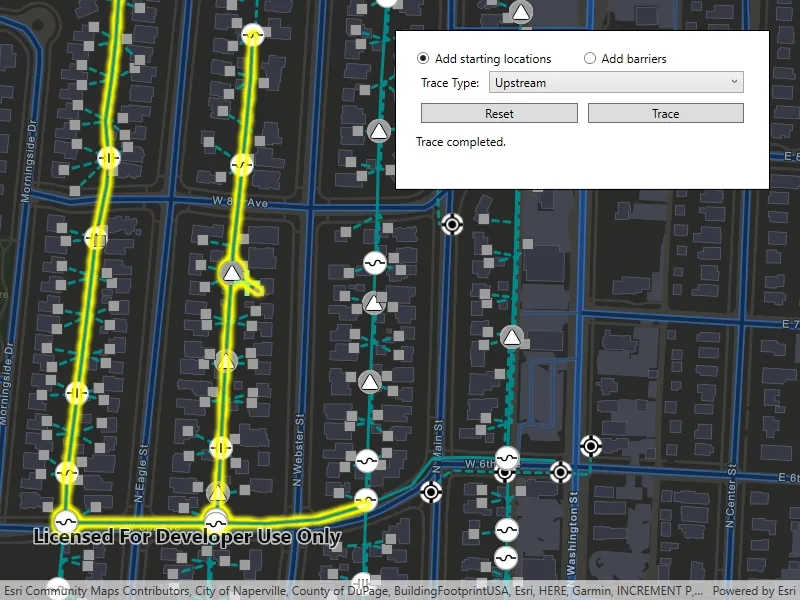
Use case
You can use a trace to visualize and validate the network topology of a utility network for quality assurance. Subnetwork traces are used for validating whether subnetworks, such as circuits or zones, are defined or edited appropriately.
How to use the sample
Tap on one or more features while ‘Add starting locations’ or ‘Add barriers’ is selected. When a junction feature is identified, you may be prompted to select a terminal. When an edge feature is identified, the distance from the tapped location to the beginning of the edge feature will be computed. Select the type of trace using the drop down menu. Click ‘Trace’ to initiate a trace on the network. Click ‘Reset’ to clear the trace parameters and start over.
How it works
- Create a
MapViewand subscribe to itsGeoViewTappedevent. - Create and load a
Mapwith a web map item URL that contains aUtilityNetwork. - Get and load the first
UtilityNetworkfrom the web map. - Get the
ServiceGeodatabasefrom the utility network and fetch the lineFeatureLayerfrom theServiceGeodatabase’s tables. - Add a
GraphicsOverlaywith symbology that distinguishes starting locations from barriers. - Identify features on the map and add a
Graphicthat represents its purpose (starting location or barrier) at the tapped location. - Create a
UtilityElementfor the identified feature. - Determine the type of this element using its
UtilityNetworkSource.SourceTypeproperty. - If the element is a junction with more than one terminal, display a terminal picker. Then set the junction’s
UtilityTerminalproperty with the selected terminal. - If an edge, set its
FractionAlongEdgeproperty usingGeometryEngine.FractionAlong. - Add this
UtilityElementto a collection of starting locations or barriers. - Create
UtilityTraceParameterswith the selected trace type along with the collected starting locations and barriers (if applicable). - Set the
UtilityTraceParameters.TraceConfigurationwith the tier’sUtilityTier.GetDefaultTraceConfiguration()result. - Run a
UtilityNetwork.TraceAsyncwith the specified parameters. - For every
FeatureLayerin the map, select the features returned withGetFeaturesForElementsAsyncfrom the elements matching theirUtilityNetworkSource.FeatureTablewith the layer’sFeatureTable.
Relevant API
- FractionAlong
- ServiceGeodatabase
- UtilityAssetType
- UtilityDomainNetwork
- UtilityElement
- UtilityElementTraceResult
- UtilityNetwork
- UtilityNetworkDefinition
- UtilityNetworkSource
- UtilityTerminal
- UtilityTier
- UtilityTraceConfiguration
- UtilityTraceParameters
- UtilityTraceResult
- UtilityTraceType
- UtilityTraversability
About the data
The Naperville Electric Web Map contains a utility network used to run the subnetwork-based trace shown in this sample. Authentication is required and handled within the sample code.
Additional information
Using utility network on ArcGIS Enterprise 10.8 requires an ArcGIS Enterprise member account licensed with the Utility Network user type extension. Please refer to the utility network services documentation.
A UtilityNetworkTraceTool component can be used for various utility network related use cases. For information about setting up the toolkit, as well as code for the component, visit the toolkit repository.
Tags
condition barriers, downstream trace, network analysis, subnetwork trace, toolkit, trace configuration, traversability, upstream trace, utility network, validate consistency
Sample code
// Copyright 2021 Esri.//// Licensed under the Apache License, Version 2.0 (the "License"); you may not use this file except in compliance with the License.// You may obtain a copy of the License at: http://www.apache.org/licenses/LICENSE-2.0//// Unless required by applicable law or agreed to in writing, software distributed under the License is distributed on an// "AS IS" BASIS, WITHOUT WARRANTIES OR CONDITIONS OF ANY KIND, either express or implied. See the License for the specific// language governing permissions and limitations under the License.
using Esri.ArcGISRuntime;using Esri.ArcGISRuntime.Data;using Esri.ArcGISRuntime.Geometry;using Esri.ArcGISRuntime.Mapping;using Esri.ArcGISRuntime.Security;using Esri.ArcGISRuntime.Symbology;using Esri.ArcGISRuntime.UI;using Esri.ArcGISRuntime.UI.Controls;using Esri.ArcGISRuntime.UtilityNetworks;using System;using System.Collections.Generic;using System.Diagnostics;using System.Linq;using System.Threading.Tasks;using System.Windows;
namespace ArcGIS.WPF.Samples.TraceUtilityNetwork{    [ArcGIS.Samples.Shared.Attributes.Sample(        name: "Trace utility network",        category: "Utility network",        description: "Discover connected features in a utility network using connected, subnetwork, upstream, and downstream traces.",        instructions: "Tap on one or more features while 'Add starting locations' or 'Add barriers' is selected. When a junction feature is identified, you may be prompted to select a terminal. When an edge feature is identified, the distance from the tapped location to the beginning of the edge feature will be computed. Select the type of trace using the drop down menu. Click 'Trace' to initiate a trace on the network. Click 'Reset' to clear the trace parameters and start over.",        tags: new[] { "condition barriers", "downstream trace", "network analysis", "subnetwork trace", "toolkit", "trace configuration", "traversability", "upstream trace", "utility network", "validate consistency" })]    [ArcGIS.Samples.Shared.Attributes.OfflineData()]    public partial class TraceUtilityNetwork    {        private const int LineLayerId = 3;        private const int DeviceLayerId = 0;        // Viewpoint in the utility network area.        private Viewpoint _startingViewpoint = new Viewpoint(new Envelope(-9812980.8041217551, 5128523.87694709, -9812798.4363710005, 5128627.6261982173, SpatialReferences.WebMercator));
        // Utility network objects.        private UtilityNetwork _utilityNetwork;        private List<UtilityElement> _startingLocations = new List<UtilityElement>();        private List<UtilityElement> _barriers = new List<UtilityElement>();        private UtilityTier _mediumVoltageTier;
        // Task completion source for the user selected terminal.        private TaskCompletionSource<UtilityTerminal> _terminalCompletionSource = null;
        // Markers for the utility elements.        private SimpleMarkerSymbol _startingPointSymbol;        private SimpleMarkerSymbol _barrierPointSymbol;
        public TraceUtilityNetwork()        {            InitializeComponent();            _ = Initialize();        }
        private async Task Initialize()        {            // As of ArcGIS Enterprise 10.8.1, using utility network functionality requires a licensed user. The following login for the sample server is licensed to perform utility network operations.            AuthenticationManager.Current.ChallengeHandler = new ChallengeHandler(async (info) =>            {                try                {                    // WARNING: Never hardcode login information in a production application. This is done solely for the sake of the sample.                    string sampleServer7User = "viewer01";                    string sampleServer7Pass = "I68VGU^nMurF";
                    return await AccessTokenCredential.CreateAsync(info.ServiceUri, sampleServer7User, sampleServer7Pass);                }                catch (Exception ex)                {                    Debug.WriteLine(ex.Message);                    return null;                }            });
            try            {                IsBusy.Visibility = Visibility.Visible;                Status.Text = "Loading Utility Network...";
                // Create a map.                MyMapView.Map = new Map(new Uri("https://sampleserver7.arcgisonline.com/portal/home/item.html?id=be0e4637620a453584118107931f718b"))                {                    InitialViewpoint = _startingViewpoint                };
                await MyMapView.Map.LoadAsync();
                _utilityNetwork = MyMapView.Map.UtilityNetworks.FirstOrDefault();                await _utilityNetwork.LoadAsync();
                var serviceGeodatabase = _utilityNetwork.ServiceGeodatabase;
                // Get the layer with electric distribution lines.                FeatureLayer lineLayer = serviceGeodatabase.GetTable(LineLayerId)?.Layer as FeatureLayer;                UniqueValue mediumVoltageValue = new UniqueValue("N/A", "Medium Voltage", new SimpleLineSymbol(SimpleLineSymbolStyle.Solid, System.Drawing.Color.DarkCyan, 3), 5);                UniqueValue lowVoltageValue = new UniqueValue("N/A", "Low Voltage", new SimpleLineSymbol(SimpleLineSymbolStyle.Dash, System.Drawing.Color.DarkCyan, 3), 3);                lineLayer.Renderer = new UniqueValueRenderer(new List<string>() { "ASSETGROUP" }, new List<UniqueValue>() { mediumVoltageValue, lowVoltageValue }, "", new SimpleLineSymbol());
                // Set the selection color for features in the map view.                MyMapView.SelectionProperties = new SelectionProperties(System.Drawing.Color.Yellow);
                // Update the trace configuration UI.                TraceTypes.ItemsSource = new List<UtilityTraceType>() { UtilityTraceType.Connected, UtilityTraceType.Subnetwork, UtilityTraceType.Upstream, UtilityTraceType.Downstream };                TraceTypes.SelectedIndex = 0;
                // Get the utility tier used for traces in this network. For this data set, the "Medium Voltage Radial" tier from the "ElectricDistribution" domain network is used.                UtilityDomainNetwork domainNetwork = _utilityNetwork.Definition.GetDomainNetwork("ElectricDistribution");                _mediumVoltageTier = domainNetwork.GetTier("Medium Voltage Radial");
                // More complex datasets may require using utility trace configurations from different tiers. The following LINQ expression gets all tiers present in the utility network.                //IEnumerable<UtilityTier> tiers = _utilityNetwork.Definition.DomainNetworks.Select(domain => domain.Tiers).SelectMany(tier => tier);
                // Create symbols for starting locations and barriers.                _startingPointSymbol = new SimpleMarkerSymbol(SimpleMarkerSymbolStyle.Cross, System.Drawing.Color.LightGreen, 25d);                _barrierPointSymbol = new SimpleMarkerSymbol(SimpleMarkerSymbolStyle.X, System.Drawing.Color.OrangeRed, 25d);
                // Create a graphics overlay.                GraphicsOverlay graphicsOverlay = new GraphicsOverlay();                MyMapView.GraphicsOverlays.Add(graphicsOverlay);
                // Set the instruction text.                Status.Text = "Click on the network lines or points to add a utility element.";            }            catch (Exception ex)            {                Status.Text = "Loading Utility Network failed...";                MessageBox.Show(ex.Message, ex.GetType().Name, MessageBoxButton.OK, MessageBoxImage.Error);            }            finally            {                MainUI.IsEnabled = true;                IsBusy.Visibility = Visibility.Hidden;            }        }
        private async void OnGeoViewTapped(object sender, GeoViewInputEventArgs e)        {            try            {                IsBusy.Visibility = Visibility.Visible;                Status.Text = "Identifying trace locations...";
                // Identify the feature to be used.                IEnumerable<IdentifyLayerResult> identifyResult = await MyMapView.IdentifyLayersAsync(e.Position, 10.0, false);                ArcGISFeature feature = identifyResult?.FirstOrDefault()?.GeoElements?.FirstOrDefault() as ArcGISFeature;                if (feature == null) { return; }
                // Create element from the identified feature.                UtilityElement element = _utilityNetwork.CreateElement(feature);
                if (element.NetworkSource.SourceType == UtilityNetworkSourceType.Junction)                {                    // Select terminal for junction feature.                    IEnumerable<UtilityTerminal> terminals = element.AssetType.TerminalConfiguration?.Terminals;                    if (terminals?.Count() > 1)                    {                        element.Terminal = await GetTerminalAsync(terminals);                    }                    Status.Text = $"Terminal: {element.Terminal?.Name ?? "default"}";                }                else if (element.NetworkSource.SourceType == UtilityNetworkSourceType.Edge)                {                    // Compute how far tapped location is along the edge feature.                    if (feature.Geometry is Polyline line)                    {                        line = line.RemoveZ() as Polyline;                        double fraction = line.FractionAlong(e.Location, -1);                        if (double.IsNaN(fraction)) { return; }                        element.FractionAlongEdge = fraction;                        Status.Text = $"Fraction along edge: {element.FractionAlongEdge}";                    }                }
                // Check whether starting location or barrier is added to update the right collection and symbology.                Symbol symbol = null;                if (IsAddingStartingLocations.IsChecked.Value == true)                {                    _startingLocations.Add(element);                    symbol = _startingPointSymbol;                }                else                {                    _barriers.Add(element);                    symbol = _barrierPointSymbol;                }
                // Add a graphic for the new utility element.                Graphic traceLocationGraphic = new Graphic(feature.Geometry as MapPoint ?? e.Location, symbol);                MyMapView.GraphicsOverlays.FirstOrDefault()?.Graphics.Add(traceLocationGraphic);            }            catch (Exception ex)            {                Status.Text = "Identifying locations failed.";                MessageBox.Show(ex.Message, ex.GetType().Name, MessageBoxButton.OK, MessageBoxImage.Error);            }            finally            {                if (Status.Text.Equals("Identifying trace locations...")) { Status.Text = "Could not identify location."; }                IsBusy.Visibility = Visibility.Hidden;            }        }
        private async Task<UtilityTerminal> GetTerminalAsync(IEnumerable<UtilityTerminal> terminals)        {            try            {                MyMapView.GeoViewTapped -= OnGeoViewTapped;                TerminalPicker.Visibility = Visibility.Visible;                MainUI.Visibility = Visibility.Collapsed;                Picker.ItemsSource = terminals;                Picker.SelectedIndex = 1;
                // Waits for user to select a terminal.                _terminalCompletionSource = new TaskCompletionSource<UtilityTerminal>();                return await _terminalCompletionSource.Task;            }            finally            {                TerminalPicker.Visibility = Visibility.Collapsed;                MainUI.Visibility = Visibility.Visible;                MyMapView.GeoViewTapped += OnGeoViewTapped;            }        }
        private void OnTerminalSelected(object sender, RoutedEventArgs e)        {            _terminalCompletionSource.TrySetResult(Picker.SelectedItem as UtilityTerminal);        }
        private void OnReset(object sender, RoutedEventArgs e)        {            // Reset the UI.            Status.Text = "Click on the network lines or points to add a utility element.";            IsBusy.Visibility = Visibility.Hidden;            TraceTypes.SelectedIndex = 0;
            // Clear collections of starting locations and barriers.            _startingLocations.Clear();            _barriers.Clear();
            // Clear the map of any locations, barriers and trace result.            MyMapView.GraphicsOverlays.FirstOrDefault()?.Graphics.Clear();            MyMapView.Map.OperationalLayers.OfType<FeatureLayer>().ToList().ForEach(layer => layer.ClearSelection());        }
        private async void OnTrace(object sender, RoutedEventArgs e)        {            try            {                // Get the selected trace type.                UtilityTraceType traceType = (UtilityTraceType)TraceTypes.SelectedItem;
                // Update the UI.                MainUI.IsEnabled = false;                IsBusy.Visibility = Visibility.Visible;                Status.Text = $"Running {traceType.ToString().ToLower()} trace...";
                // Clear previous selection from the layers.                MyMapView.Map.OperationalLayers.OfType<FeatureLayer>().ToList().ForEach(layer => layer.ClearSelection());
                // Build trace parameters.                UtilityTraceParameters parameters = new UtilityTraceParameters(traceType, _startingLocations);                foreach (UtilityElement barrier in _barriers)                {                    parameters.Barriers.Add(barrier);                }
                // Set the trace configuration using the tier from the utility domain network.                parameters.TraceConfiguration = _mediumVoltageTier.GetDefaultTraceConfiguration();
                //  Get the trace result from the utility network.                IEnumerable<UtilityTraceResult> traceResult = await _utilityNetwork.TraceAsync(parameters);                UtilityElementTraceResult elementTraceResult = traceResult?.FirstOrDefault() as UtilityElementTraceResult;
// Check if there are any elements in the result. if (elementTraceResult?.Elements?.Count > 0) { foreach (FeatureLayer layer in MyMapView.Map.OperationalLayers.OfType<FeatureLayer>()) { IEnumerable<UtilityElement> elements = elementTraceResult.Elements.Where(element => element.NetworkSource.Name == layer.FeatureTable.TableName); IEnumerable<Feature> features = await _utilityNetwork.GetFeaturesForElementsAsync(elements); layer.SelectFeatures(features); } } Status.Text = "Trace completed."; } catch (Exception ex) { Status.Text = "Trace failed..."; if (ex is ArcGISServerException && ex.Message == null) { MessageBox.Show("Trace failed.", ex.GetType().Name, MessageBoxButton.OK, MessageBoxImage.Error); } else { MessageBox.Show(ex.Message, ex.GetType().Name, MessageBoxButton.OK, MessageBoxImage.Error); } } finally { MainUI.IsEnabled = true; IsBusy.Visibility = Visibility.Hidden; } } }}<UserControl x:Class="ArcGIS.WPF.Samples.TraceUtilityNetwork.TraceUtilityNetwork" xmlns="http://schemas.microsoft.com/winfx/2006/xaml/presentation" xmlns:x="http://schemas.microsoft.com/winfx/2006/xaml" xmlns:esri="http://schemas.esri.com/arcgis/runtime/2013"> <Grid> <esri:MapView x:Name="MyMapView" GeoViewTapped="OnGeoViewTapped" /> <Border x:Name="MainUI" HorizontalAlignment="Right" VerticalAlignment="Top" IsEnabled="False" Style="{StaticResource BorderStyle}"> <Grid> <Grid.RowDefinitions> <RowDefinition /> <RowDefinition /> <RowDefinition /> <RowDefinition /> <RowDefinition /> </Grid.RowDefinitions> <Grid.ColumnDefinitions> <ColumnDefinition /> <ColumnDefinition /> </Grid.ColumnDefinitions> <RadioButton x:Name="IsAddingStartingLocations" Content="Add starting locations" GroupName="AddState" IsChecked="True" /> <RadioButton Grid.Column="1" Content="Add barriers" GroupName="AddState" /> <Grid Grid.Row="1" Grid.ColumnSpan="2" HorizontalAlignment="Stretch" VerticalAlignment="Center"> <Grid.ColumnDefinitions> <ColumnDefinition Width="auto" /> <ColumnDefinition Width="*" /> </Grid.ColumnDefinitions> <TextBlock Grid.Column="0" Margin="5" VerticalAlignment="Center" Text="Trace Type:" /> <ComboBox x:Name="TraceTypes" Grid.Column="1" Margin="5" HorizontalContentAlignment="Stretch" /> </Grid> <Button Grid.Row="2" Margin="5" Click="OnReset" Content="Reset" /> <Button Grid.Row="2" Grid.Column="1" Margin="5" Click="OnTrace" Content="Trace" /> <TextBlock x:Name="Status" Grid.Row="3" Grid.ColumnSpan="2" Margin="0,5,0,5" Text="Loading sample..." /> <ProgressBar x:Name="IsBusy" Grid.Row="4" Grid.ColumnSpan="2" Height="15" IsIndeterminate="True" Visibility="Collapsed" /> </Grid> </Border>
<Border Name="TerminalPicker" HorizontalAlignment="Center" VerticalAlignment="Center" Style="{StaticResource BorderStyle}" Visibility="Collapsed"> <Grid> <Grid.RowDefinitions> <RowDefinition /> <RowDefinition /> <RowDefinition /> </Grid.RowDefinitions> <TextBlock Grid.Row="0" Margin="5" Text="Select the terminal for this junction." /> <ComboBox x:Name="Picker" Grid.Row="1" Margin="5"> <ComboBox.ItemTemplate> <DataTemplate> <TextBlock Text="{Binding Name}" /> </DataTemplate> </ComboBox.ItemTemplate> </ComboBox> <Button Grid.Row="2" Margin="5" Click="OnTerminalSelected" Content="Select" /> </Grid> </Border> </Grid></UserControl>