Class GeometryServerImplClass
[Guid("0C38B104-A3A8-4BDE-858F-4231430F2101")]
[ClassInterface(ClassInterfaceType.None)]
public class GeometryServerImplClass : GeometryServerImpl, IObjectConstruct, IRequestHandler2, IRequestHandler, IObjectActivate, ILogSupport, ISupportErrorInfo, IGeometryServer3, IGeometryServer2, IGeometryServer- Inheritance
-
GeometryServerImplClass
- Implements
- Inherited Members
Constructors
GeometryServerImplClass()
public GeometryServerImplClass()Explicit Interface Implementations
Activate()
Activates the object.
virtual void Activate()AutoComplete(ISpatialReference, IPolygonArray, IPolylineArray)
Discovers polygons bounded by existing polygons and input linework.
virtual IPolygonArray AutoComplete(ISpatialReference pSR, IPolygonArray pInPolygons, IPolylineArray pCompletionLines)Parameters
pSRISpatialReferencepInPolygonsIPolygonArraypCompletionLinesIPolylineArray
Returns
Buffer(ISpatialReference, ISpatialReference, ISpatialReference, IDoubleArray, IUnit, bool, IGeometryArray)
Buffers an array of geometries by each distance specified in an array of distances. The distance units can optionally be specified. Geometries buffered at a given distance can optionally be unioned together.
virtual IGeometryArray Buffer(ISpatialReference pInSR, ISpatialReference pBufferSR, ISpatialReference pOutSR, IDoubleArray pDistances, IUnit pUnit, bool bUnion, IGeometryArray pInGeometries)Parameters
pInSRISpatialReferencepBufferSRISpatialReferencepOutSRISpatialReferencepDistancesIDoubleArraypUnitIUnitbUnionboolpInGeometriesIGeometryArray
Returns
Remarks
Applies the geometric buffer operation to each geometry in pInGeometries, using each distance in the array pDistances. All geometries are assumed to be in the coordinate system pInSR, which cannot be nil. pBufferSR is the spatial reference in which the geometries are buffered. pOutSR is the spatial reference in which the buffer polygons are returned. pInSR must be specified. Either or both of the other SRs can be null. If the output spatial reference is null, then the input spatial reference is used for output; if the buffering spatial reference is null, then the output spatial reference is used for buffering; if both output and buffer spatial references are null, then the input spatial reference is used.
The distances can be specified in a separate unit of measure. For example, the buffer distances could be specified in feet and the coordinates of the geometries could be specified in meters. If bUnion is false, each buffered polygon will be added to ppOutBuffers separately. If bUnion is true, then all geometries buffered at a given distance will be unioned into a single (possibly multipart) polygon and that unioned geometry will be placed in the output array.
The SpatialReference property for all returned geometry will be null. It is the consumers responsibility to assign the spatial reference to each geometry returned, if desired. In this case, the spatial reference is assumed to be the output spatial reference defined for the Buffer operation.
Refer to IGeometryServer for additional details on how the input spatial reference is interpreted.
Buffering of geometries with latitude-longitude coordinates is only supported for points and multipoints. In order to meaningfully buffer polylines and polygons with such coordinates, you need to specify a planar (projected) coordinate system in which the buffering will happen. Use the BufferSpatialReference parameter to define this coordinate system. When the Buffer method is called, the input features will be projected into this coordinate system (BufferSpatialReference), buffered, and then either inverse projected into the original coordinate system (InSpatialReference) or projected into the output coordinate system (OutSpatialReference).
When buffering points or multipoints and the input spatial reference is a geographic coordinate system (WGS1984, for example), you have the option of generating true geodesic buffers. To obtain such buffers, specify a linear unit of distance for the pUnit parameter.
Here is an example showing how to create a buffer using the Geometry Server.
BufferGeodesic(ISpatialReference, ISpatialReference, IDoubleArray, double, ILinearUnit, bool, IGeometryArray)
Constructs true buffer regions around Points, lines and polygons using true geodesic distances and directions.
virtual IGeometryArray BufferGeodesic(ISpatialReference pInSR, ISpatialReference pOutSR, IDoubleArray pDistances, double bufferDeviation, ILinearUnit pLinearDistanceUnit, bool bUnion, IGeometryArray pInGeometries)Parameters
pInSRISpatialReferencepOutSRISpatialReferencepDistancesIDoubleArraybufferDeviationdoublepLinearDistanceUnitILinearUnitbUnionboolpInGeometriesIGeometryArray
Returns
Remarks
If
are in geographic coordinate system, then
geometries
needs to be set to
geodesic
in order to generate a buffer polygon using a geodesic distance. The
true
input parameter will be ignored when
bufferSR
is set to
geodesic
.true
Construct(IPropertySet)
Two phase object construction.
virtual void Construct(IPropertySet props)Parameters
propsIPropertySet
ConvexHull(ISpatialReference, IGeometryArray)
Computes the convex hull of the input geometries
virtual IGeometry ConvexHull(ISpatialReference pSR, IGeometryArray pInGeometryArray)Parameters
pSRISpatialReferencepInGeometryArrayIGeometryArray
Returns
Remarks
The convex hull of a set of points, polylines and polygons is shown below. If all the inputs are collinear, than a polyline will be returned instead of a polygon. If all inputs are located at a single point, then that point will be returned.

Cut(ISpatialReference, IGeometryArray, IPolyline, out ILongArray)
Cuts the target polyline or polygon Cutter.
virtual IGeometryArray Cut(ISpatialReference pSR, IGeometryArray pTargets, IPolyline pCutter, out ILongArray ppCutIndexes)Parameters
pSRISpatialReferencepTargetsIGeometryArraypCutterIPolylineppCutIndexesILongArray
Returns
Remarks
The target of the cut operation may be either a polyline or a polygon.
When it is a polyline, it is split where it intersects the cutter polyline. Each piece is classified as ‘left of’ or ‘right of’ the cutter. This classification is based on the orientation of the cutter line. The left pieces are returned in the first element of the output array and the right pieces are returned in the second element. Parts of the target polyline that do not intersect the cutting polyline are discarded. Figure below shows an example. The orientation of the cutter line is indicated with a red arrowhead. Notice that a polyline part is also cut when the cutter line just touches it (as opposed to crossing it). The lower right input part was not included in the output because it did not intersect the cutting line. The cutting line can also have multiple parts. The left/right decision is made per part.

The next figure shows an example of a cutting operation with a multipart cutting polyline. The orientation of each cutting part is shown with a red arrowhead. The ‘left’ result has been requested and is shown in the right box of the figure.

When the target is a polygon, the left/right classification it not done. The polygon pieces are returned in order of ascending area. In the figure below, the first cut part returned is to the right of the oriented cutting line, but it has the smallest area. Input parts that do not intersect the cutting line are discarded. The cutting line can be multi-part. See figure below.

Deactivate()
Deactivates the object.
virtual void Deactivate()Densify(ISpatialReference, IGeometryArray, double, bool, double)
Applies the ArcObjects 'Densify' operation to each element of the geometry array.
virtual IGeometryArray Densify(ISpatialReference pSR, IGeometryArray pInGeometries, double maxSegmentLength, bool useDeviationDensification, double densificationParameter)Parameters
pSRISpatialReferencepInGeometriesIGeometryArraymaxSegmentLengthdoubleuseDeviationDensificationbooldensificationParameterdouble
Returns
Remarks
Replaces each curve segment, and optionally each line segment, in a polyline or polygon with line segments. Other types of input geometries will be ignored. All geometries are assumed to be in the spatial reference pSR, which cannot be nil.
When maxSegmentLength is greater than zero, lines and curves greater than that length will be replaced with lines at most maxSegmentLength long, and curves shorter than that will be replaced with lines connecting their endpoints. If maxSegmentLength is 0, then only curve segments will be densified, as explained below.
In general, this method provides three ways to densify curves:
- based on length
- based on central angle
- based on maximum distance of replacement line from input curve (deviation)
The following table explains how the input parameters work together.
| When MaxSegmentLength is | and angleOrDeviation is | then |
|---|---|---|
| > 0 | 0 | All segments longer than maxSegmentLength are replaced with sequences of lines no longer than maxSegmentLength. Curves shorter than maxSegmentLength are replaced with lines connecting the curve endpoints. This is method 1, above, for densifying curves. |
| 0 | > 0 | Input lines are copied to the output geometries. Input curves are densified using either method 2 or method 3, based on the value of the useDeviationDensification parameter. |
| > 0 | > 0 | Lines longer than maxSegmentLength units are replaced with sequences of lines no longer than maxSegmentLength; curves are replaced with sequences of lines using either method 2 or method 3, based on the value of the useDeviationDensification parameter. |
When UseDeviationDensification is false the DensificationParameter is interpreted as a central angle, instead of a deviation.
Refer to IGeometryServer for additional details on how the input spatial reference is interpreted.
If the geometries are in a geographic coordinate system, then “linear” densification distances are in units of degrees (or some other gcs angular unit). This isn’t meaningful if you expect output segments to have a constant ground length, but it still accomplishes the purpose of densifying the geometries, which is useful if you subsequently want to project them more accurately.
DensifyGeodesic(ISpatialReference, IGeometryArray, double, ILinearUnit)
Densifies geometries by plotting points along the geodesics between existing vertices (uses IPolycurve4::GeodesicDensify).
virtual IGeometryArray DensifyGeodesic(ISpatialReference pSR, IGeometryArray pInGeometries, double maxSegmentLength, ILinearUnit pLengthUnit)Parameters
pSRISpatialReferencepInGeometriesIGeometryArraymaxSegmentLengthdoublepLengthUnitILinearUnit
Returns
Remarks
Densifies each polyline or polygon in the input array by plotting points along the geodesic paths between existing vertices. MaxSegmentLength is expressed in some linear unit of measure. If the LengthUnit parameter is specified, then MaxSegmentLength is expressed in those units. If the LengthUnit parameter is not specified, then MaxSegmentLength is expressed in the the linear units of the input spatial reference, if the spatial reference is a projected coordinate system. Otherwise, it is assumed to be expressed in meters.
If the spatial reference is a projected coordinate system, then the input geometries will be inversed projected, geodesic path points will be plotted, and the result will be forward projected into the same spatial reference.
The figure below illustrates the DensifyGeodesic operation applied to a polyline with 3 vertices, with a max output segment length of 10,000 meters.

Difference(ISpatialReference, IGeometryArray, IGeometry)
Returns an array of geometries where each result geometry R[i] is (array1[i] difference G2).
virtual IGeometryArray Difference(ISpatialReference pSR, IGeometryArray pInGA1, IGeometry pInG2)Parameters
pSRISpatialReferencepInGA1IGeometryArraypInG2IGeometry
Returns
Remarks
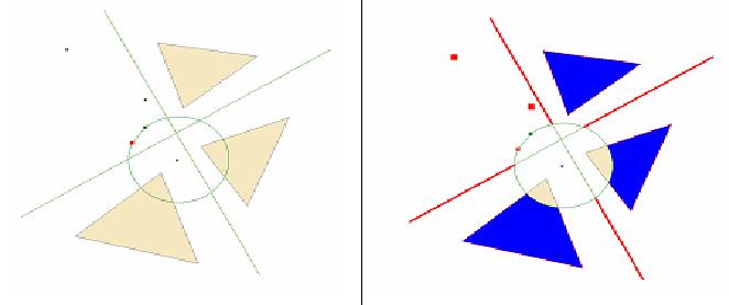
This operation constructs the set-theoretic difference between each element of the input array and InGeometry2. Each result is placed at the corresponding index in the output array – that is, Result[i] = InGeometryArray1[i] Difference InGeometry2. The only restriction on combinations of geometry types is that the dimension of InGeometry2 must be equal to or greater than the dimensions of the elements of InGeometryArray1. Any inputs that are completely within InGeometry2 are represented by empty geometries of the same type in the output array.
The figure below shows an example of the difference operation. The geometry array contains all geometries shown with the exception of the central circular polygon. The output array contains the modified geometries shown in the right part of the figure. Note that one of the output points will be “empty” because the corresponding input is inside the circular polygon.
FindSRByWKID(string, int, int, bool, bool)
Defines an SR based upon its well known identifier (WKID) and optionally a WKID for a vertical datum. The resolution and xy tolerances are either computed from the sr horizon or set to defaults. 'authority' is typically either 'EPSG' or 'Esri'.
virtual ISpatialReference FindSRByWKID(string authority, int wkid, int WKID_Z, bool bDefaultXYResolution, bool bDefaultXYTolerance)Parameters
Returns
Remarks
Returns a predefined, high precision spatial reference based on its OGP/EPSG Well Known Identifier (WKID, aka “factory code”). Valid WKIDs are listed below. If WKID_Z > -1, then a vertical coordinate system will be created and associated with the horizontal coordinate system.
AuthorityName is usually "EPSG" or "ESRI", but can
also be an arbitrary string. It can also be the empty string if you
want the default authority name associated with the new spatial
reference. Clients can associate their own authority names with
factory codes that are currently associated with the EPSG or ESRI
authority names, because only the WKID is used to create the
spatial reference. Here are the current rules for mapping
WKID ranges to default authority names:
• A WKID in the EPSG code range (1000
– 32768) will result in an AUTHORITY name of
“EPSG”, and the version will be the current EPSG
version used (currently “6.12”).
• A WKID in the ESRI code range (33000 –
199999) will result in an AUTHORITY name of “ESRI”, and
the version will be the current PE library version (currently
“9.3”).
• A WKID in the user (objedit) range (200000
– 209199) will result in an AUTHORITY name of
“CUSTOM”, with no version associated with it.
This name is specified by the OGC.
For web service clients of the geometry server, the returned WKT (well known text) element of the spatial reference will have an “AUTHORITY’ tag in it, containing the default or the client-specified authority name and the specified WKID.
If bDefaultXYResolution is true, then the xy coordinate grid resolution will be set to its default value (see SetDefaultXYResolution for details). If it is false, the finest possible resolution that covers the horizon of the spatial reference will be used (see ConstructFromHorizon for details).
If bDefaultXYTolerance is true, then the default xy tolerance of 1mm will be used (see SetDefaultXYTolerance for details). If it is false, then the minimum xy tolerance will be used (2.0 * xy coordinate grid resolution).
Lists of the valid WKIDs for predefined Projected
Coordinate Systems can be found here:
esriSRProjCS2Type,
esriSRProjCS3Type,
esriSRProjCS4Type,
esriSRProjCSType
Lists of the valid WKIDs for predefined Geographic Coordinate Systems can be found here:
esriSRGeoCS2Type, esriSRGeoCS3Type, esriSRGeoCSType
Default XY Resolution values
|
SpatialReference type |
Precision |
Default value |
|
ProjectedCoordinateSystem |
high |
1/10 mm |
|
ProjectedCoordinateSystem |
low |
1 mm |
|
GeographicCoordinateSystem |
high |
1/10,000 arc-second |
|
GeographicCoordinateSystem |
low |
1/500 arc-second |
|
UnknownCoordinateSystem |
high |
1/10 mm |
|
UnknownCoordinateSystem |
low |
1 mm |
Defining an XY resolution
Defining an XY resolution for a spatial reference depends on the
type and precision of a coordinate system. For high precision
spatial references, the domain extent and resolution must be
sufficient to cover the horizon of a given coordinate system.
For low-precision spatial references the domain extent is
centered on the horizon center.
For a high precision ProjectedCoordinateSystem (PCS), the domain extent is a square completely covering, and slightly larger than, the horizon extent of the PCS (which is an arbitrary rectangle). The scale factor (1/precision) is chosen to fit this domain. For a low precision PCS, the center of the domain extent is aligned with the center of the horizon extent and expanded to achieve a target resolution of 1mm.
For a high precision GeographicCoordinateSystem (GCS), the square domain (-400, -400, 400, 400), expressed in the units of the spatial reference, is used. For a low precision GCS the upper right hand corner is adjusted to achieve a default resolution of 1/500 of an arc-second.
For an UnknownCoordinateSystem (UCS), the "horizon" is defined to be a square that produces a resolution of 1 millimeter for a low precision UCS or 1/10 mm for a high precision UCS.
Default XY Tolerance calculations
For a ProjectedCoordinateSystem or an UnknownCoordinateSystem, the
default tolerance is 1 mm (expressed in the units of the spatial
reference) or 2.0 * XYResolution, whichever is larger. For a
GeographicCoordinateSystem, it is the angle subtending 1 mm at the
equator, or 2.0 * XYResolution, whichever is larger.
The minimum allowable XYTolerance is 2.0 * XYResolution.
If the default XY tolerance is not greater than or
equal to 2.0 * XYResolution, the XYTolerance will be set at 2.0 *
XYResolution.
FindSRByWKT(string, string, bool, bool)
Defines a spatial reference object based upon its well known text string (WKT) and optionally a WKT for a vertical datum. The resolution and xy tolerances are either computed from the sr horizon or set to defaults. The output sr is always high precision.
virtual ISpatialReference FindSRByWKT(string wkt, string WKT_Z, bool bDefaultXYResolution, bool bDefaultXYTolerance)Parameters
Returns
Remarks
Finds a predefined spatial reference based on its OGC/EPSG
definition string, otherwise known as its well-known text string
(WKT). The text string contains individual parameters
of a spatial reference. A valid spatial reference for a
geographic coordinate system (GEOGCS) may appears as
follows:
GEOGCS["GCS_WGS_1984",DATUM["D_WGS_1984",SPHEROID["WGS_1984",6378137.0,298.257223563]],PRIMEM["Greenwich",0.0],UNIT["Degree",0.0174532925199433]]
Note the nested structure of parameters includes a datum, spheriod,
prime meridian, and angular unit.
A valid spatial reference for a projected coordinate system
(PROJCS) may appears as follows:
PROJCS["World_Mercator",GEOGCS["GCS_WGS_1984",DATUM["D_WGS_1984",SPHEROID["WGS_1984",6378137.0,298.257223563]],PRIMEM["Greenwich",0.0],UNIT["Degree",0.0174532925199433]],
PROJECTION["Mercator"],PARAMETER["False_Easting",0.0],PARAMETER["False_Northing",0.0],PARAMETER["Central_Meridian",0.0],PARAMETER["Standard_Parallel_1",0.0],UNIT["Meter",1.0]]]
Note the nested structure of parameters includes a geographic
coordinate system (GEOGCS), a projection, and a set of projection
parameters such as false easting, false northing, and standard
parallel.
If
WKT_Z is specified and not empty, then a vertical
coordinate system will be created and associated with the
horizontal coordinate system. The definition string can be
generated from ArcObjects using the ExportToESRISpatialReference
method on a PCS or GCS. The boolean parameters are as described for
FindSRByWKID.
FindUnitsByWKID(string, int)
Defines a unit object based upon its well known identified (WKID). 'authority' is typically either 'EPSG' or 'Esri'.
virtual IUnit FindUnitsByWKID(string authority, int wkid)Parameters
Returns
Remarks
Finds a predefined linear or angular unit of measure based on its OGP/EPSG well known identifier (WKID, also referred to as “factory code”). AuthorityName is optional. If specified, it is usually either "EPSG" or "ESRI", but can also be an arbitrary string. As with spatial references, only the WKID value is used to locate the predefined unit. The WKIDs for predefined linear and angular units are listed here: esriSRUnit2Type, esriSRUnitType.
The Unit returned is often used in other Geometry service methods such as Buffer.
FindUnitsByWKT(string)
Defines a unit object based upon its well known text string.
virtual IUnit FindUnitsByWKT(string wkt)Parameters
wktstring
Returns
Remarks
Finds a predefined linear or angular unit of measure based on its well known text string (WKT). The Unit returned is often used in other Geometry service methods such as Buffer.
Here are some examples of WKT strings for linear and angular
units.
U.S. Survey Foot:
UNIT["Foot_US",0.3048006096012192,AUTHORITY["EPSG",9003]]
Arc-minute:
UNIT["Minute",0.0002908882086657216,AUTHORITY["EPSG",9103]]
Creating custom
units
You can create a custom unit in ArcObjects by using the
ImportFromESRISpatialReference method on an
existing linear or angular unit object. Web service clients
can do this by creating a LinearUnit or AngularUnit value first and
then assigning the WKT string to the WKT property of the value. The
example script in this topic illustrates the former approach and
the example provided in the IGeometryServer
topic illustrates the latter.Generalize(ISpatialReference, IGeometryArray, double, ILinearUnit)
Returns generalized (Douglas-Peucker) versions of the input polylines and polygons (uses IPolycurve::Generalize).
virtual IGeometryArray Generalize(ISpatialReference pSR, IGeometryArray pInGA, double maxDeviation, ILinearUnit pDeviationUnit)Parameters
pSRISpatialReferencepInGAIGeometryArraymaxDeviationdoublepDeviationUnitILinearUnit
Returns
Remarks
The Generalize operation applies Douglas-poiker line generalization to each element of the input array. The results are placed in corresponding indexes of the output array. If DeviationUnit is specified, then MaxDeviation is expressed in those units, otherwise it is expressed in the units of the spatial reference.
GetAreasAndLengths(ISpatialReference, IPolygonArray, out IDoubleArray, out IDoubleArray)
Calculates areas and perimeter lengths for each polygon in the specified array.
virtual void GetAreasAndLengths(ISpatialReference pSR, IPolygonArray pInPolygons, out IDoubleArray ppAreas, out IDoubleArray ppLengths)Parameters
pSRISpatialReferencepInPolygonsIPolygonArrayppAreasIDoubleArrayppLengthsIDoubleArray
Remarks
All geometries are assumed to be defined in the spatial reference pSR, which cannot be nil. The area and length values are computed in that spatial reference. It is not recommended that this method be used on geometries associated with a geographic coordinate system, since the length would then be calculated in units of "degrees" and the area would be calculated in units of "square degrees".
Refer to IGeometryServer for additional details on how the input spatial reference is interpreted.
GetAreasAndLengths2(ISpatialReference, IPolygonArray, ILinearUnit, ILinearUnit, esriAreaUnits, out IDoubleArray, out IDoubleArray)
Calculates areas and perimeter lengths for each polygon in the specified array. Optionally does unit conversion.
virtual void GetAreasAndLengths2(ISpatialReference pSR, IPolygonArray pInPolygons, ILinearUnit pLengthUnit, ILinearUnit pAreaUnit, esriAreaUnits areaUnitEnum, out IDoubleArray ppAreas, out IDoubleArray ppLengths)Parameters
pSRISpatialReferencepInPolygonsIPolygonArraypLengthUnitILinearUnitpAreaUnitILinearUnitareaUnitEnumesriAreaUnitsppAreasIDoubleArrayppLengthsIDoubleArray
Remarks
The area and length values are computed in the units specified as input parameters, if they are present, otherwise they are computed in the units of the spatial reference. It is not recommended that this method be used on geometries having latitude-longitude coordinates. You can use the GetLengthsGeodesic method to compute accurate lengths for polylines with latitude-longitude coordinates.
GetAreasAndLengthsGeodesic(ISpatialReference, IPolygonArray, ILinearUnit, ILinearUnit, esriAreaUnits, out IDoubleArray, out IDoubleArray)
Returns true geodesic area and geodesic perimeter length for each input polygon.
virtual void GetAreasAndLengthsGeodesic(ISpatialReference pSR, IPolygonArray pPolygons, ILinearUnit pLengthUnit, ILinearUnit pAreaUnit, esriAreaUnits areaUnitEnum, out IDoubleArray ppAreas, out IDoubleArray ppLengths)Parameters
pSRISpatialReferencepPolygonsIPolygonArraypLengthUnitILinearUnitpAreaUnitILinearUnitareaUnitEnumesriAreaUnitsppAreasIDoubleArrayppLengthsIDoubleArray
Remarks
Use this method if you want to calculate an area or length using only the vertices of the polygon and define the lines between the points as geodesic segments independent of the actual shape of the polygon. A geodesic segment is the shortest path between two points on an ellipsoid.
The returned areas and lengths are expressed in the specified area units and linear units, if present, or in the units of the spatial reference. If AreaUnit and LengthUnit are not specified and the input spatial reference is a geographic coordinate system, then the lengths and areas are expressed in meters. This method calculates the ellipsoidal shortest path distance between each pair of the vertices in the polylines.
The spatial reference can be a projected or a geographic coordinate system. If the former, then the geometries are first inverse projected into its associated geographic coordinate system and then the distance calculations are performed.
GetAreasAndLengthsPreserveShape(ISpatialReference, IPolygonArray, ILinearUnit, ILinearUnit, esriAreaUnits, out IDoubleArray, out IDoubleArray)
Returns true area and perimeter length for each input polygon.
virtual void GetAreasAndLengthsPreserveShape(ISpatialReference pSR, IPolygonArray pPolygons, ILinearUnit pLengthUnit, ILinearUnit pAreaUnit, esriAreaUnits areaUnitEnum, out IDoubleArray ppAreas, out IDoubleArray ppLengths)Parameters
pSRISpatialReferencepPolygonsIPolygonArraypLengthUnitILinearUnitpAreaUnitILinearUnitareaUnitEnumesriAreaUnitsppAreasIDoubleArrayppLengthsIDoubleArray
Remarks
The method calculates the area or length of the geometry on the surface of the Earth ellipsoid, for geometry defined in projected or geographic coordinate system. This method preserves the shape of the geometry in its coordinate system. This means the true area or length will be calculated for the geometry you see in the map. (What you see is what you get.)
The returned lengths and areas are expressed in the specified linear units and area units, if present, or in the units of the spatial reference. If AreaUnit and LengthUnit are not specified and the input spatial reference is a geographic coordinate system, then the lengths and areas are expressed in meters.
GetDistance(ISpatialReference, IGeometry, IGeometry, ILinearUnit)
Reports shortest distance between G1 and G2.
virtual double GetDistance(ISpatialReference pSR, IGeometry pG1, IGeometry pG2, ILinearUnit pDistanceUnit)Parameters
pSRISpatialReferencepG1IGeometrypG2IGeometrypDistanceUnitILinearUnit
Returns
Remarks
The distance value is computed in the specified linear units, if present, or in the units of the spatial reference. It is not recommended that this method be used on geometries with lat-long coordinates. Use GetDistanceGeodesic instead.
GetDistanceGeodesic(ISpatialReference, IGeometry, IGeometry, ILinearUnit)
Reports the shortest geodesic distance between G1 and G2.
virtual double GetDistanceGeodesic(ISpatialReference pSR, IGeometry pG1, IGeometry pG2, ILinearUnit pDistanceUnit)Parameters
pSRISpatialReferencepG1IGeometrypG2IGeometrypDistanceUnitILinearUnit
Returns
Remarks
The distance value is computed in the specified linear units, if present, or in the units of the spatial reference. If SpatialReference is a projected coordinate system, the input geometries will first be inverse projected and then shortest geodesic distance will be computed on the latitude-longitude coordinates.
GetLabelPoints(ISpatialReference, IPolygonArray)
Calculates an interior point for each polygon.
virtual IPointArray GetLabelPoints(ISpatialReference pSR, IPolygonArray pInPolygons)Parameters
pSRISpatialReferencepInPolygonsIPolygonArray
Returns
Remarks
Generates one point geometry per input polygon. Each point is guaranteed to be inside its corresponding polygon. The ArcObjects IArea::LabelPoint property is used to generate the output points. All input geometries are assumed to be defined in the input spatial reference pSR. pSR cannot be nil.
GetLengths(ISpatialReference, IPolylineArray)
Calculates the length of eacch polyline in the specified array.
virtual IDoubleArray GetLengths(ISpatialReference pSR, IPolylineArray pInPolylines)Parameters
pSRISpatialReferencepInPolylinesIPolylineArray
Returns
Remarks
All geometries are assumed to be
defined in the spatial reference pSR, which cannot be nil. The
length values are computed in that spatial reference. It is not
recommended that this method be used on geometries associated with
a geographic coordinate system, since the length would then be
calculated in units of "degrees".
You can use the GetLengthsGeodesic method to compute accurate
lengths for polylines with latitude-longitude
coordinates.
Refer to IGeometryServer for additional details on how the input spatial reference is interpreted.
GetLengths2(ISpatialReference, IPolylineArray, ILinearUnit)
Calculates the length of eacch polyline in the specified array. Optionally does unit conversion.
virtual IDoubleArray GetLengths2(ISpatialReference pSR, IPolylineArray pInPolylines, ILinearUnit pLengthUnit)Parameters
pSRISpatialReferencepInPolylinesIPolylineArraypLengthUnitILinearUnit
Returns
Remarks
The length values are computed in the specified linear units, if present, or in the units of the spatial reference. It is not recommended that this method be used on geometries having latitude-longitude coordinates, since the length would then be calculated in units of "degrees". You can use the GetLengthsGeodesic method to compute accurate lengths for polylines with latitude-longitude coordinates.
GetLengthsGeodesic(ISpatialReference, IPolylineArray, ILinearUnit)
Returns geodesic length of each Polyline.
virtual IDoubleArray GetLengthsGeodesic(ISpatialReference pSR, IPolylineArray polylines, ILinearUnit pLengthUnit)Parameters
pSRISpatialReferencepolylinesIPolylineArraypLengthUnitILinearUnit
Returns
Remarks
The returned lengths are expressed in the specified linear units, if present, or in the units of the spatial reference. If LengthUnit is not specified and the input spatial reference is a geographic coordinate system, then the lengths are expressed in meters. This method calculates the ellipsoidal shortest path distance between each pair of the vertices in the polylines.
The spatial reference can be a projected or a geographic coordinate system. If the former, then the geometries are first inverse projected into its associated geographic coordinate system and then the distance calculations are performed.
GetLengthsPreserveShape(ISpatialReference, IPolylineArray, ILinearUnit)
Returns true length of each polyline.
virtual IDoubleArray GetLengthsPreserveShape(ISpatialReference pSR, IPolylineArray polylines, ILinearUnit pLengthUnit)Parameters
pSRISpatialReferencepolylinesIPolylineArraypLengthUnitILinearUnit
Returns
Remarks
The method calculates the length of the geometry on the surface of the Earth ellipsoid, for geometry defined in projected or geographic coordinate system. This method preserves the shape of the geometry in its coordinate system. This means the true length will be calculated for the geometry you see in the map. (What you see is what you get.)
The returned lengths are expressed in the specified linear units, if present, or in the units of the spatial reference. If LengthUnit is not specified and the input spatial reference is a geographic coordinate system, then the lengths are expressed in meters.
HandleBinaryRequest(ref byte[])
Handles a binary request.
virtual byte[] HandleBinaryRequest(ref byte[] request)Parameters
requestbyte[]
Returns
- byte[]
HandleBinaryRequest2(string, ref byte[])
Handles a binary request with explicit capabilities.
virtual byte[] HandleBinaryRequest2(string Capabilities, ref byte[] request)Parameters
Returns
- byte[]
HandleStringRequest(string, string)
Handles a SOAP string request.
virtual string HandleStringRequest(string Capabilities, string request)Parameters
Returns
IGeometryServer2_Buffer(ISpatialReference, ISpatialReference, ISpatialReference, IDoubleArray, IUnit, bool, IGeometryArray)
virtual IGeometryArray IGeometryServer2_Buffer(ISpatialReference pInSR, ISpatialReference pBufferSR, ISpatialReference pOutSR, IDoubleArray pDistances, IUnit pUnit, bool bUnion, IGeometryArray pInGeometries)Parameters
pInSRISpatialReferencepBufferSRISpatialReferencepOutSRISpatialReferencepDistancesIDoubleArraypUnitIUnitbUnionboolpInGeometriesIGeometryArray
Returns
IGeometryServer2_Densify(ISpatialReference, IGeometryArray, double, bool, double)
virtual IGeometryArray IGeometryServer2_Densify(ISpatialReference pSR, IGeometryArray pInGeometries, double maxSegmentLength, bool useDeviationDensification, double densificationParameter)Parameters
pSRISpatialReferencepInGeometriesIGeometryArraymaxSegmentLengthdoubleuseDeviationDensificationbooldensificationParameterdouble
Returns
IGeometryServer2_FindSRByWKID(string, int, int, bool, bool)
virtual ISpatialReference IGeometryServer2_FindSRByWKID(string authority, int wkid, int WKID_Z, bool bDefaultXYResolution, bool bDefaultXYTolerance)Parameters
Returns
IGeometryServer2_FindSRByWKT(string, string, bool, bool)
virtual ISpatialReference IGeometryServer2_FindSRByWKT(string wkt, string WKT_Z, bool bDefaultXYResolution, bool bDefaultXYTolerance)Parameters
Returns
IGeometryServer2_FindUnitsByWKID(string, int)
virtual IUnit IGeometryServer2_FindUnitsByWKID(string authority, int wkid)Parameters
Returns
IGeometryServer2_FindUnitsByWKT(string)
virtual IUnit IGeometryServer2_FindUnitsByWKT(string wkt)Parameters
wktstring
Returns
IGeometryServer2_GetAreasAndLengths(ISpatialReference, IPolygonArray, out IDoubleArray, out IDoubleArray)
virtual void IGeometryServer2_GetAreasAndLengths(ISpatialReference pSR, IPolygonArray pInPolygons, out IDoubleArray ppAreas, out IDoubleArray ppLengths)Parameters
pSRISpatialReferencepInPolygonsIPolygonArrayppAreasIDoubleArrayppLengthsIDoubleArray
IGeometryServer2_GetLabelPoints(ISpatialReference, IPolygonArray)
virtual IPointArray IGeometryServer2_GetLabelPoints(ISpatialReference pSR, IPolygonArray pInPolygons)Parameters
pSRISpatialReferencepInPolygonsIPolygonArray
Returns
IGeometryServer2_GetLengths(ISpatialReference, IPolylineArray)
virtual IDoubleArray IGeometryServer2_GetLengths(ISpatialReference pSR, IPolylineArray pInPolylines)Parameters
pSRISpatialReferencepInPolylinesIPolylineArray
Returns
IGeometryServer2_Project(ISpatialReference, ISpatialReference, esriTransformDirection, ITransformation, IEnvelope, IGeometryArray)
virtual IGeometryArray IGeometryServer2_Project(ISpatialReference pInSR, ISpatialReference pOutSR, esriTransformDirection xFormDir, ITransformation pXForm, IEnvelope pExtent, IGeometryArray pInGeometries)Parameters
pInSRISpatialReferencepOutSRISpatialReferencexFormDiresriTransformDirectionpXFormITransformationpExtentIEnvelopepInGeometriesIGeometryArray
Returns
IGeometryServer2_Relation(ISpatialReference, IGeometryArray, IGeometryArray, esriSpatialRelationEnum, string)
virtual IRelationResultArray IGeometryServer2_Relation(ISpatialReference pSR, IGeometryArray pInGA1, IGeometryArray pInGA2, esriSpatialRelationEnum r, string param)Parameters
pSRISpatialReferencepInGA1IGeometryArraypInGA2IGeometryArrayresriSpatialRelationEnumparamstring
Returns
IGeometryServer2_Simplify(ISpatialReference, IGeometryArray)
virtual IGeometryArray IGeometryServer2_Simplify(ISpatialReference pSR, IGeometryArray pInGeometries)Parameters
pSRISpatialReferencepInGeometriesIGeometryArray
Returns
IGeometryServer3_AutoComplete(ISpatialReference, IPolygonArray, IPolylineArray)
virtual IPolygonArray IGeometryServer3_AutoComplete(ISpatialReference pSR, IPolygonArray pInPolygons, IPolylineArray pCompletionLines)Parameters
pSRISpatialReferencepInPolygonsIPolygonArraypCompletionLinesIPolylineArray
Returns
IGeometryServer3_Buffer(ISpatialReference, ISpatialReference, ISpatialReference, IDoubleArray, IUnit, bool, IGeometryArray)
virtual IGeometryArray IGeometryServer3_Buffer(ISpatialReference pInSR, ISpatialReference pBufferSR, ISpatialReference pOutSR, IDoubleArray pDistances, IUnit pUnit, bool bUnion, IGeometryArray pInGeometries)Parameters
pInSRISpatialReferencepBufferSRISpatialReferencepOutSRISpatialReferencepDistancesIDoubleArraypUnitIUnitbUnionboolpInGeometriesIGeometryArray
Returns
IGeometryServer3_ConvexHull(ISpatialReference, IGeometryArray)
virtual IGeometry IGeometryServer3_ConvexHull(ISpatialReference pSR, IGeometryArray pInGeometryArray)Parameters
pSRISpatialReferencepInGeometryArrayIGeometryArray
Returns
IGeometryServer3_Cut(ISpatialReference, IGeometryArray, IPolyline, out ILongArray)
virtual IGeometryArray IGeometryServer3_Cut(ISpatialReference pSR, IGeometryArray pTargets, IPolyline pCutter, out ILongArray ppCutIndexes)Parameters
pSRISpatialReferencepTargetsIGeometryArraypCutterIPolylineppCutIndexesILongArray
Returns
IGeometryServer3_Densify(ISpatialReference, IGeometryArray, double, bool, double)
virtual IGeometryArray IGeometryServer3_Densify(ISpatialReference pSR, IGeometryArray pInGeometries, double maxSegmentLength, bool useDeviationDensification, double densificationParameter)Parameters
pSRISpatialReferencepInGeometriesIGeometryArraymaxSegmentLengthdoubleuseDeviationDensificationbooldensificationParameterdouble
Returns
IGeometryServer3_DensifyGeodesic(ISpatialReference, IGeometryArray, double, ILinearUnit)
virtual IGeometryArray IGeometryServer3_DensifyGeodesic(ISpatialReference pSR, IGeometryArray pInGeometries, double maxSegmentLength, ILinearUnit pLengthUnit)Parameters
pSRISpatialReferencepInGeometriesIGeometryArraymaxSegmentLengthdoublepLengthUnitILinearUnit
Returns
IGeometryServer3_Difference(ISpatialReference, IGeometryArray, IGeometry)
virtual IGeometryArray IGeometryServer3_Difference(ISpatialReference pSR, IGeometryArray pInGA1, IGeometry pInG2)Parameters
pSRISpatialReferencepInGA1IGeometryArraypInG2IGeometry
Returns
IGeometryServer3_FindSRByWKID(string, int, int, bool, bool)
virtual ISpatialReference IGeometryServer3_FindSRByWKID(string authority, int wkid, int WKID_Z, bool bDefaultXYResolution, bool bDefaultXYTolerance)Parameters
Returns
IGeometryServer3_FindSRByWKT(string, string, bool, bool)
virtual ISpatialReference IGeometryServer3_FindSRByWKT(string wkt, string WKT_Z, bool bDefaultXYResolution, bool bDefaultXYTolerance)Parameters
Returns
IGeometryServer3_FindUnitsByWKID(string, int)
virtual IUnit IGeometryServer3_FindUnitsByWKID(string authority, int wkid)Parameters
Returns
IGeometryServer3_FindUnitsByWKT(string)
virtual IUnit IGeometryServer3_FindUnitsByWKT(string wkt)Parameters
wktstring
Returns
IGeometryServer3_Generalize(ISpatialReference, IGeometryArray, double, ILinearUnit)
virtual IGeometryArray IGeometryServer3_Generalize(ISpatialReference pSR, IGeometryArray pInGA, double maxDeviation, ILinearUnit pDeviationUnit)Parameters
pSRISpatialReferencepInGAIGeometryArraymaxDeviationdoublepDeviationUnitILinearUnit
Returns
IGeometryServer3_GetAreasAndLengths(ISpatialReference, IPolygonArray, out IDoubleArray, out IDoubleArray)
virtual void IGeometryServer3_GetAreasAndLengths(ISpatialReference pSR, IPolygonArray pInPolygons, out IDoubleArray ppAreas, out IDoubleArray ppLengths)Parameters
pSRISpatialReferencepInPolygonsIPolygonArrayppAreasIDoubleArrayppLengthsIDoubleArray
IGeometryServer3_GetAreasAndLengths2(ISpatialReference, IPolygonArray, ILinearUnit, ILinearUnit, esriAreaUnits, out IDoubleArray, out IDoubleArray)
virtual void IGeometryServer3_GetAreasAndLengths2(ISpatialReference pSR, IPolygonArray pInPolygons, ILinearUnit pLengthUnit, ILinearUnit pAreaUnit, esriAreaUnits areaUnitEnum, out IDoubleArray ppAreas, out IDoubleArray ppLengths)Parameters
pSRISpatialReferencepInPolygonsIPolygonArraypLengthUnitILinearUnitpAreaUnitILinearUnitareaUnitEnumesriAreaUnitsppAreasIDoubleArrayppLengthsIDoubleArray
IGeometryServer3_GetDistance(ISpatialReference, IGeometry, IGeometry, ILinearUnit)
virtual double IGeometryServer3_GetDistance(ISpatialReference pSR, IGeometry pG1, IGeometry pG2, ILinearUnit pDistanceUnit)Parameters
pSRISpatialReferencepG1IGeometrypG2IGeometrypDistanceUnitILinearUnit
Returns
IGeometryServer3_GetDistanceGeodesic(ISpatialReference, IGeometry, IGeometry, ILinearUnit)
virtual double IGeometryServer3_GetDistanceGeodesic(ISpatialReference pSR, IGeometry pG1, IGeometry pG2, ILinearUnit pDistanceUnit)Parameters
pSRISpatialReferencepG1IGeometrypG2IGeometrypDistanceUnitILinearUnit
Returns
IGeometryServer3_GetLabelPoints(ISpatialReference, IPolygonArray)
virtual IPointArray IGeometryServer3_GetLabelPoints(ISpatialReference pSR, IPolygonArray pInPolygons)Parameters
pSRISpatialReferencepInPolygonsIPolygonArray
Returns
IGeometryServer3_GetLengths(ISpatialReference, IPolylineArray)
virtual IDoubleArray IGeometryServer3_GetLengths(ISpatialReference pSR, IPolylineArray pInPolylines)Parameters
pSRISpatialReferencepInPolylinesIPolylineArray
Returns
IGeometryServer3_GetLengths2(ISpatialReference, IPolylineArray, ILinearUnit)
virtual IDoubleArray IGeometryServer3_GetLengths2(ISpatialReference pSR, IPolylineArray pInPolylines, ILinearUnit pLengthUnit)Parameters
pSRISpatialReferencepInPolylinesIPolylineArraypLengthUnitILinearUnit
Returns
IGeometryServer3_GetLengthsGeodesic(ISpatialReference, IPolylineArray, ILinearUnit)
virtual IDoubleArray IGeometryServer3_GetLengthsGeodesic(ISpatialReference pSR, IPolylineArray polylines, ILinearUnit pLengthUnit)Parameters
pSRISpatialReferencepolylinesIPolylineArraypLengthUnitILinearUnit
Returns
IGeometryServer3_Intersect(ISpatialReference, IGeometryArray, IGeometry)
virtual IGeometryArray IGeometryServer3_Intersect(ISpatialReference pSR, IGeometryArray pInGA1, IGeometry pInG2)Parameters
pSRISpatialReferencepInGA1IGeometryArraypInG2IGeometry
Returns
IGeometryServer3_Offset(ISpatialReference, IGeometryArray, double, ILinearUnit, int, double)
virtual IGeometryArray IGeometryServer3_Offset(ISpatialReference pSR, IGeometryArray pInGA, double offsetDistance, ILinearUnit pOffsetUnit, int offsetHow, double bevelRatio)Parameters
pSRISpatialReferencepInGAIGeometryArrayoffsetDistancedoublepOffsetUnitILinearUnitoffsetHowintbevelRatiodouble
Returns
IGeometryServer3_Project(ISpatialReference, ISpatialReference, esriTransformDirection, ITransformation, IEnvelope, IGeometryArray)
virtual IGeometryArray IGeometryServer3_Project(ISpatialReference pInSR, ISpatialReference pOutSR, esriTransformDirection xFormDir, ITransformation pXForm, IEnvelope pExtent, IGeometryArray pInGeometries)Parameters
pInSRISpatialReferencepOutSRISpatialReferencexFormDiresriTransformDirectionpXFormITransformationpExtentIEnvelopepInGeometriesIGeometryArray
Returns
IGeometryServer3_Relation(ISpatialReference, IGeometryArray, IGeometryArray, esriSpatialRelationEnum, string)
virtual IRelationResultArray IGeometryServer3_Relation(ISpatialReference pSR, IGeometryArray pInGA1, IGeometryArray pInGA2, esriSpatialRelationEnum r, string param)Parameters
pSRISpatialReferencepInGA1IGeometryArraypInGA2IGeometryArrayresriSpatialRelationEnumparamstring
Returns
IGeometryServer3_Reshape(ISpatialReference, IGeometry, IPolyline)
virtual IGeometry IGeometryServer3_Reshape(ISpatialReference pSR, IGeometry pTarget, IPolyline pReshaper)Parameters
pSRISpatialReferencepTargetIGeometrypReshaperIPolyline
Returns
IGeometryServer3_Simplify(ISpatialReference, IGeometryArray)
virtual IGeometryArray IGeometryServer3_Simplify(ISpatialReference pSR, IGeometryArray pInGeometries)Parameters
pSRISpatialReferencepInGeometriesIGeometryArray
Returns
IGeometryServer3_TrimExtend(ISpatialReference, IPolylineArray, IPolyline, int)
virtual IPolylineArray IGeometryServer3_TrimExtend(ISpatialReference pSR, IPolylineArray pInPA, IPolyline pTrimExtendTo, int extendHow)Parameters
pSRISpatialReferencepInPAIPolylineArraypTrimExtendToIPolylineextendHowint
Returns
IGeometryServer3_Union(ISpatialReference, IGeometryArray)
virtual IGeometry IGeometryServer3_Union(ISpatialReference pSR, IGeometryArray pInGA)Parameters
pSRISpatialReferencepInGAIGeometryArray
Returns
IRequestHandler2_HandleBinaryRequest(ref byte[])
virtual byte[] IRequestHandler2_HandleBinaryRequest(ref byte[] request)Parameters
requestbyte[]
Returns
- byte[]
IRequestHandler2_HandleStringRequest(string, string)
virtual string IRequestHandler2_HandleStringRequest(string Capabilities, string request)Parameters
Returns
InitLogging(ILog)
Initializes an object with a log.
virtual void InitLogging(ILog Log)Parameters
LogILog
InterfaceSupportsErrorInfo(ref Guid)
virtual void InterfaceSupportsErrorInfo(ref Guid riid)Parameters
riidGuid
Intersect(ISpatialReference, IGeometryArray, IGeometry)
Returns an array of geometries where each result geometry R[i] is (array1[i] intersect G2. If G2 is an Envelope, then this is clipping.
virtual IGeometryArray Intersect(ISpatialReference pSR, IGeometryArray pInGA1, IGeometry pInG2)Parameters
pSRISpatialReferencepInGA1IGeometryArraypInG2IGeometry
Returns
Remarks
This operation constructs the set-theoretic intersection between each element of the input array and InGeometry2. Each result is placed at the corresponding index in the output array – that is, Result[i] = InGeometryArray1[i] Intersect InGeometry2. If inGeometryArray1[i] and InGeometry2 disjoint, the output is an empty geometry of the type with the minimum dimension between inGeometryArray1[i] and InGeometry2.
The figure below shows an example of the intersect operation. The input geometry array contains all geometries shown on the left of the figure with the exception of the central circular polygon. The output array contains the modified geometries shown in the right part of the figure. Note that two of the output points will be “empty” because their corresponding inputs are outside the circular polygon.

Offset(ISpatialReference, IGeometryArray, double, ILinearUnit, int, double)
Returns an array of polylines and polygons that are offset versions of the input polylines and polygons (uses ITopologicalOperator::ConstructOffset).
virtual IGeometryArray Offset(ISpatialReference pSR, IGeometryArray pInGA, double offsetDistance, ILinearUnit pOffsetUnit, int offsetHow, double bevelRatio)Parameters
pSRISpatialReferencepInGAIGeometryArrayoffsetDistancedoublepOffsetUnitILinearUnitoffsetHowintbevelRatiodouble
Returns
Remarks
The offset operation creates a geometry that is a constant distance from an input polyline or polygon. It is similar to buffering, but produces a one sided result. If offsetDistance > 0, then the offset geometry is constructed to the right of the oriented input geometry, otherwise it is constructed to the left. For a polygon, the orientation of outer rings is clockwise and for inner rings it is counter clockwise. So the “right side” of a polygon is always its inside.
bevelRatio is multiplied by the offset distance and the result determines how far a mitered offset intersection can be from the input curve before it is beveled or rounded. When esriGeometryOffsetMitered is specified, the input bevel ratio is ignored and 10 is used internally.When esriGeometryOffsetBevelled is specified, 1.1 will be used if bevelRatio is not specified.
The figures below show some examples of offsetting polylines. The red arrowhead shows the orientation of the input polyline.

Project(ISpatialReference, ISpatialReference, esriTransformDirection, ITransformation, IEnvelope, IGeometryArray)
Projects an array of geometries from their current spatial reference (pInSR) to a destination spatial reference (pOutSR). The projection process can optionally include a datum transformation if the source and destination SRs have different GCSs.
virtual IGeometryArray Project(ISpatialReference pInSR, ISpatialReference pOutSR, esriTransformDirection xFormDir, ITransformation pXForm, IEnvelope pExtent, IGeometryArray pInGeometries)Parameters
pInSRISpatialReferencepOutSRISpatialReferencexFormDiresriTransformDirectionpXFormITransformationpExtentIEnvelopepInGeometriesIGeometryArray
Returns
Remarks
The Project method applies the projection pOutSR to a copy of each element of pInGeometries and places the results in ppProjectedGeometries. All input geometries are assumed to be in the spatial reference pInSR, which cannot be nil. The input geometries are not modified. The array can contain mixed top-level geometry types (specifically points, multipoints, polylines and polygons). The array can also contain envelopes. pXForm and pExtent are optional. If pXForm is specified, then it is an instance of a GeoTransformation subclass (see EDN for details on datum transformations), and xFormDir must also be specified (
esriTransformForwardesriTransformReverseThe SpatialReference property for all returned geometries will be null. It is the consumers responsibility to assign the spatial reference to each geometry returned, if desired. In this case, the spatial reference is assumed to be the output spatial reference defined for the Project operation.
If pXForm is not specified and the datums of the specified spatial references are not the same, then a search is made through a set of default datum transformations (a.k.a geographic transformations) . Currently, the following transformations, identified by name and WKID, are in that set:
•
esriSRGeoTransformation_NAD_1927_TO_NAD_1983_NADCON•
esriSRGeoTransformation_NAD1983_To_WGS1984_1•
esriSRGeoTransformation_NAD1927_To_WGS1984_4Refer to FindSRByWKID for a discussion on how to create the different kinds of spatial reference systems that can be used with this method. In addition, Well Known Identifiers (WKIDs) for available geotransformations are listed in the following enumerations:
esriSRGeoTransformation2Type
esriSRGeoTransformation3Type
esriSRGeoTransformationType
Refer to GeometryServer for additional details on how the input spatial reference is interpreted.
Relation(ISpatialReference, IGeometryArray, IGeometryArray, esriSpatialRelationEnum, string)
Determines the pairs of geometries from the input geometry arrays that participate in the specified spatial relation.
virtual IRelationResultArray Relation(ISpatialReference pSR, IGeometryArray pInGA1, IGeometryArray pInGA2, esriSpatialRelationEnum r, string param)Parameters
pSRISpatialReferencepInGA1IGeometryArraypInGA2IGeometryArrayresriSpatialRelationEnumparamstring
Returns
Remarks
Computes the set of pairs of geometries from pInGA1 and pInGA2 that belong to the specified relation. Both arrays are assumed to be in the coordinate system pSR, which cannot be nil. The relations are evaluated in 2D. Z coordinates are not used. Geometry types cannot be mixed within an array. Further restrictions on the types of geometries in an array are listed in the following table. r is a member of esriSpatialRelationEnum and can be one of the following:
| Name | Description |
|---|---|
| esriSpatialRelationDisjoint | Same as IRelationalOperator::Disjoint. The zero-based index of a geometry from pInGA1 and the zero-based index of a geometry from pInGA2 define an element of the output array of relation results if the geometries share no points in common. See IRelationalOperator_Disjoint for some examples of the disjoint relation. There are no additional restrictions on the types of geometries in the input arrays. |
| esriSpatialRelationIntersection | The opposite of esriSpatialRelationDisjoint. An element of the output array will specify the indexes of geometries from the input arrays if they share at least one point in the xy plane. There are no additional restrictions on the types of geometries in the input arrays. |
| esriSpatialRelationInteriorIntersection | Same as esriSpatialRelationIntersection, but excludes intersections that occur only at boundaries (two touching polygons for example). The interior of a point is considered to be the point itself and the interior of a polyline excludes the endpoints of all its parts. There are no additional restrictions on the types of geometries in the input arrays. |
| esriSpatialRelationIn, esriSpatialRelationWithin | These relations are similar. esriSpatialRelationIn is the same as IRelationalOperator::Within. esriSpatialRelationWithin is the same but also allows polylines that are strictly on the boundaries of polygons to be considered “in” the polygon. This case is disallowed by the former relation (and disallowed by IRelationalOperator::Within). The dimension of all geometries in pInGA1 must be >= the dimension of geometries in pInGA2. |
|
esriSpatialRelationPointTouch, esriSpatialRelationLineTouch, esriSpatialRelationTouch |
esriSpatialRelationPointTouch and esriSpatialRelationLineTouch are boundary intersections classified by dimension of intersection. esriSpatialRelationTouch is the union of those two and is equivalent to the ArcObjects IRelationalOperator Touch method. These relations are defined for polylines and polygons. |
| esriSpatialRelationLineCoincidence | The boundaries of the shapes must share a 1D intersection, but the relationship between the interiors of the shapes is not considered (they could overlap, one could be contained in the other, or their interiors could be disjoint). This relation applies to polylines and polygons. |
| esriSpatialRelationCross | Same as the ArcObjects IRelationalOperator::Cross method. Lines can cross other lines at a point and lines can cross polygons. See IRelationalOperator_Crosses for examples. |
| esriSpatialRelationRelation | 'param' defines the 'Shape Comparison Language' string to be evaluated. Strings such as "RELATE(G1, G2, ""FFFTTT***"")" are accepted, in addition to other kinds of strings. See the following EDN topic for more details on the Shape Comparison Language. http://edndoc.esri.com/arcobjects/9.2/NET/40de6491-9b2d-440d-848b-2609efcd46b1.htm |
The output array contains elements of type
struct esriRelationPair { // The index of the left element in the relation. long m_leftIndex;//The index of the right element in the relation. long m_rightIndex;
} esriRelationPair;
m_leftIndex is a zero-based index into pInGA1 and
m_rightIndex is an index into pInGA2.
esriGeometryRelationEnum is a synonym for esriSpatialRelationEnum. The former is the type name exposed through the web service. The latter is exposed through the COM api.
Refer to IGeometryServer for additional details on how the input spatial reference is interpreted.
Reshape(ISpatialReference, IGeometry, IPolyline)
Reshapes the target polyline or polygon. The reshaping polyline can have only one part. If the target was not reshaped, an empty geometry of the saem type is returned.
virtual IGeometry Reshape(ISpatialReference pSR, IGeometry pTarget, IPolyline pReshaper)Parameters
pSRISpatialReferencepTargetIGeometrypReshaperIPolyline
Returns
Remarks
Reshapes the target polyline or polygon. The reshaping polyline can have only one part. If the reshaper does not intersect the target polyline, or does not define a closed loop for the target polygon, then an empty geometry of the same type as the target geometry is returned. The orientation of the reshaper is not considered. The following rules for polygon and polyline reshaping are used:
Polygons:. only one ring (part) is explicitly reshaped – the first one in index order that intersects the reshaping path. The longest portion of the original ring boundary is preserved. The reshaped polygon is re-simplified after the reshape operation has been applied, so the rules for simplification will determine what happens if multiple rings interact with the reshaping path. The graphics show how preserving the longest portion of the boundary can invert the ring in some cases. If more complicated reshaping behavior is desired, a combination of auto-complete, cutting and union can be used.

Polylines: multiple paths (parts) can be affected by the reshaping path. The following graphics show three cases. The polyline being reshaped has part sequence and part orientations shown in red in the upper left graphic. The reshape is shown on the left of each row. The result is shown on the right of each row.

Simplify(ISpatialReference, IGeometryArray)
Applies the ArcObjects 'Simplify' operation to each element of the geometry array.
virtual IGeometryArray Simplify(ISpatialReference pSR, IGeometryArray pInGeometries)Parameters
pSRISpatialReferencepInGeometriesIGeometryArray
Returns
Remarks
Applies the ArcObjects geometric simplification operation to a copy of each geometry in the input array, placing the result in ppSimplifiedGeometries. The input geometries are assumed to be specified in the input spatial reference pSR, which cannot be nil. The elements can be a mixture of points, multipoints, polylines or polygons. Elements that can’t be simplifed are replaced with empty geometries of the same type at the corresponding index entry in the output array.
Refer to IGeometryServer for additional details on how the input spatial reference is interpreted.
This operation uses the coordinate grid and the xy and z cluster tolerances of the spatial reference. For more information on these properties and how they can affect your coordinates, please refer to the ESRI whitepaper “Understanding Coordinate Management in the Geodatabase”: http://support.esri.com/index.cfm?fa=knowledgebase.whitepapers.viewPaper&PID=43&MetaID=1301
Simplify alters the input geometry making its definition
"topologically legal" with respect to its geometry type:
-
For Points, Simplify does nothing. A point has no constraints on
the values of its coordinates.
-
For Multipoints, Simplify snaps all X, Y, Z, and M coordinates to the grid of the associated spatial reference (defined by the spatial reference’s false origin and xyUnits), then removes identical points. A point is identical to another point when the two have identical X and Y coordinates (after snapping), and when attributes for which it is aware are identical to the attributes for which the other point is aware. For example, if both points are Z aware, the Z coordinate values must be identical.

-
Polylines are simplified using the SimplifyNetwork
method. Coordinates
are snapped, zero-length segments and empty parts are removed.
Length is determined in 3D if the polyline has z coordinates,
otherwise it is determined in 2D.
-
For Polygons, Simplify identifies an interior and exterior for the polygon, then modifies the polygon structure to be consistent with that determination. The methodology for identifying interior and exterior is:
1. Remove all dangles
2. Identify the largest legal rings, add them to the output version of the polygon, then delete them from the working version
3. Repeat
This operation uses the xy cluster tolerance of the associated spatial reference to determine when two vertices are the same, or when a vertex needs to be snapped to a line. This specific approach is subject to change in future releases of esri software.
At the end of Simplify, no rings will overlap, no self intersection will occur (except in certain circumstances) and, in general, an arbitrary point can always be classified unambiguously as either outside, on the boundary of, or inside the polygon. All exterior rings are oriented clockwise. All interior rings (i.e. holes) are counter-clockwise.

TrimExtend(ISpatialReference, IPolylineArray, IPolyline, int)
Trims or extends each polyline in the input array using TrimExtendTo (uses IConstructCurve::ConstructExtended for extension operation).
virtual IPolylineArray TrimExtend(ISpatialReference pSR, IPolylineArray pInPA, IPolyline pTrimExtendTo, int extendHow)Parameters
pSRISpatialReferencepInPAIPolylineArraypTrimExtendToIPolylineextendHowint
Returns
Remarks
Trims (cuts) polylines that intersect the trim-extend line, or extends polylines to it that don’t intersect it. See the figure below for some examples. The details of how polylines are extended can be controlled by adding together combinations of the values listed in the table below.
values to be used with the trim-extend operation
|
Value |
Description |
|
|
esriDefaultCurveExtension |
0 |
By default, extension considers both ends of paths. The old ends remain and new points are added at the extended ends. The new points have attributes that are extrapolated from adjacent existing segments. |
|
esriRelocateEnds |
1 |
If an extension is performed at an end, relocate the end point to the new position instead of leaving the old point and adding a new point at the new position. |
|
esriKeepEndAttributes |
2 |
If an extension is performed at an end, do not extrapolate the end-segment's attributes for the new point. Instead, make its attributes the same as the current end. Incompatible with esriNoAttributes. |
|
esriNoEndAttributes |
4 |
If an extension is performed at an end, do not extrapolate the end-segment's attributes for the new point. Instead, make its attributes be empty. Incompatible with esriKeepAttributes. |
|
esriNoExtendAtFrom |
8 |
Do not extend the 'from' end of any path. |
|
esriNoExtendAtTo |
16 |
Do not extend the 'to' end of any path. |

Union(ISpatialReference, IGeometryArray)
Returns the topological union of the input geometries (uses ITopologicalOperator::ConstructUnion). The input geometries must have the same dimension (0d, 1d, 2d).
virtual IGeometry Union(ISpatialReference pSR, IGeometryArray pInGA)Parameters
pSRISpatialReferencepInGAIGeometryArray
Returns
Remarks
This operation constructs the set-theoretic union of the geometries in the input array. All inputs must be of the same type.
