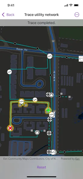
Discover connected features in a utility network using connected, subnetwork, upstream, and downstream traces.
Use case
You can use a trace to visualize and validate the network topology of a utility network for quality assurance. Subnetwork traces are used for validating whether subnetworks, such as circuits or zones, are defined or edited appropriately.
How to use the sample
Tap “Start a new trace” to select the type of trace using the confirmation dialogue. Tap on one or more features while “Start” or “Barrier” is selected. When a junction feature is identified, you may be prompted to select a terminal. When an edge feature is identified, the distance from the tapped location to the beginning of the edge feature will be computed. Tap “Trace” to initiate a trace on the network. Tap “Reset” to clear the trace parameters and start over.
How it works
- Create a
MapViewwith aMapthat contains utility networks. - Add a
GraphicsOverlayto hold symbology that distinguishes starting locations from barriers. - Get and load the first
UtilityNetworkfrom the web map. - Get the
ServiceGeodatabasefrom the utility network and fetch the lineFeatureLayerfrom theServiceGeodatabase’s tables for customized renderer. - Allow users to choose a trace type from the set of
UtilityTraceParameters.TraceType(s). - Create
UtilityTraceParameterswith the selected trace type. - Set the
UtilityTraceConfigurationwith the utility tier’sdefaultTraceConfigurationproperty. - Use the
onSingleTapGesturemodifier to listen for tap events on the map view. - Identify tapped features on the map and add a
Graphicthat represents its purpose (starting point or barrier) at the tapped location. - Create a
UtilityElementfor the identified feature. - Determine the type of the identified feature using
UtilityNetworkSource.sourceType. - If the type is
junction, display a terminal picker when more than one terminal is found. - If the type is
edge, compute how far along the edge the user tapped usingGeometryEngine.polyline(_:fractionalLengthClosestTo:tolerance:). - Add any created
UtilityElement(s) to the collection of starting locations or barriers in theUtilityTraceParameters. - Run
UtilityNetwork.trace(using:)using theUtilityTraceParameters. - Group the
UtilityElementTraceResult.elementsby theirnetworkSource.name. - For every
FeatureLayerin this map with trace result elements, select features by convertingUtilityElement(s) toArcGISFeature(s) usingUtilityNetwork.features(for:).
Relevant API
- GeometryEngine.polyline(_:fractionalLengthClosestTo:tolerance:)
- ServiceGeodatabase
- UtilityAssetType
- UtilityDomainNetwork
- UtilityElement
- UtilityElementTraceResult
- UtilityNetwork
- UtilityNetworkDefinition
- UtilityNetworkSource
- UtilityTerminal
- UtilityTier
- UtilityTraceConfiguration
- UtilityTraceParameters
- UtilityTraceResult
- UtilityTraceType
- UtilityTraversability
Additional information
The Naperville electrical network feature service, hosted on ArcGIS Online, contains a utility network used to run the subnetwork-based trace shown in this sample.
A UtilityNetworkTrace toolkit component can be used for various utility network related use cases. For information about setting up the toolkit, as well as code for the underlying component, visit the toolkit repository.
Tags
condition barriers, downstream trace, network analysis, subnetwork trace, toolkit, trace configuration, traversability, upstream trace, utility network, validate consistency
Sample code
// Copyright 2023 Esri//// Licensed under the Apache License, Version 2.0 (the "License");// you may not use this file except in compliance with the License.// You may obtain a copy of the License at////   https://www.apache.org/licenses/LICENSE-2.0//// Unless required by applicable law or agreed to in writing, software// distributed under the License is distributed on an "AS IS" BASIS,// WITHOUT WARRANTIES OR CONDITIONS OF ANY KIND, either express or implied.// See the License for the specific language governing permissions and// limitations under the License.
import ArcGISimport SwiftUI
struct TraceUtilityNetworkView: View {    /// The view model for the sample.    @StateObject var model = Model()
    var body: some View {        MapViewReader { mapViewProxy in            MapView(                map: model.map,                viewpoint: .initialViewpoint,                graphicsOverlays: [model.points]            )            .onSingleTapGesture { screenPoint, mapPoint in                model.lastSingleTap = (screenPoint, mapPoint)            }            .selectionColor(.yellow)            .onTeardown {                model.tearDown()            }            .overlay(alignment: .center) {                if model.tracingActivity == .traceRunning,                   let type = model.pendingTraceParameters?.traceType {                    VStack {                        Text("Running \(String(describing: type)) trace")                        ProgressView()                            .progressViewStyle(.circular)                    }                    .padding(6)                    .background(.thinMaterial)                    .clipShape(.rect(cornerRadius: 10))                }            }            .overlay(alignment: .top) {                if let hint = model.hint {                    Text(hint)                        .frame(maxWidth: .infinity)                        .padding(.vertical, 6)                        .background(.thinMaterial, ignoresSafeAreaEdges: .horizontal)                }            }            .task {                await model.setup()            }            .task(id: model.lastSingleTap?.mapPoint) {                guard case .settingPoints = model.tracingActivity,                      let lastSingleTap = model.lastSingleTap else {                    return                }                if let feature = try? await mapViewProxy.identifyLayers(                    screenPoint: lastSingleTap.screenPoint,                    tolerance: 10                ).first?.geoElements.first as? ArcGISFeature {                    model.add(feature, at: lastSingleTap.mapPoint)                }            }            .task(id: model.tracingActivity) {                model.updateUserHint()                if model.tracingActivity == .traceRunning {                    do {                        try await model.trace()                        model.tracingActivity = .traceCompleted                    } catch {                        model.tracingActivity = .traceFailed(description: error.localizedDescription)                    }                }            }            .toolbar {                ToolbarItemGroup(placement: .bottomBar) {                    traceMenu                }            }        }    }}
extension TraceUtilityNetworkView {    /// The trace types supported for this sample.    var supportedTraceTypes: [UtilityTraceParameters.TraceType] {        return [.connected, .subnetwork, .upstream, .downstream]    }}
private extension Viewpoint {    /// The initial viewpoint to be displayed when the sample is first opened.    static var initialViewpoint: Viewpoint {        .init(            boundingGeometry: Envelope(                xRange: (-9813547.35557238)...(-9813185.0602376),                yRange: (5129980.36635111)...(5130215.41254146)            )        )    }}
#Preview {    NavigationStack {        TraceUtilityNetworkView()    }}
// Copyright 2023 Esri//// Licensed under the Apache License, Version 2.0 (the "License");// you may not use this file except in compliance with the License.// You may obtain a copy of the License at//// https://www.apache.org/licenses/LICENSE-2.0//// Unless required by applicable law or agreed to in writing, software// distributed under the License is distributed on an "AS IS" BASIS,// WITHOUT WARRANTIES OR CONDITIONS OF ANY KIND, either express or implied.// See the License for the specific language governing permissions and// limitations under the License.
extension TraceUtilityNetworkView { /// The types of points used during a utility network trace. enum PointType: String { /// A point which marks a location for a trace to stop. case barrier /// A point which marks a location for a trace to begin. case start
/// A displayable name the point type. var label: String { switch self { case .barrier: return "Barrier" case .start: return "Start" } } }
/// The different states of a utility network trace. enum TracingActivity: Equatable { /// Starting points and barriers are being added. case settingPoints(pointType: PointType) /// The trace completed successfully. case traceCompleted /// The trace failed. case traceFailed(description: String) /// The trace is running. case traceRunning }}// Copyright 2023 Esri//// Licensed under the Apache License, Version 2.0 (the "License");// you may not use this file except in compliance with the License.// You may obtain a copy of the License at//// https://www.apache.org/licenses/LICENSE-2.0//// Unless required by applicable law or agreed to in writing, software// distributed under the License is distributed on an "AS IS" BASIS,// WITHOUT WARRANTIES OR CONDITIONS OF ANY KIND, either express or implied.// See the License for the specific language governing permissions and// limitations under the License.
import ArcGISimport UIKit.UIColor
extension TraceUtilityNetworkView { /// The model used to manage the state of the trace view. @MainActor class Model: ObservableObject { // MARK: Properties
/// The domain network for this sample. private var electricDistribution: UtilityDomainNetwork? { network.definition?.domainNetwork(named: "ElectricDistribution") }
/// The textual hint shown to the user. @Published var hint: String?
/// The last element that was added to either the list of starting points or barriers. /// /// When an element contains more than one terminal, the user should be presented with the /// option to select a terminal. Keeping a reference to the last added element provides ease /// of access to save the user's choice. @Published var lastAddedElement: UtilityElement?
/// The last locations in the screen and map where a tap occurred. /// /// Monitoring these values allows for an asynchronous identification task when they change. @Published var lastSingleTap: (screenPoint: CGPoint, mapPoint: Point)?
/// The map contains the utility network and operational layers on which trace results will /// be selected. let map = Map(item: .napervilleElectricNetwork())
/// The utility tier for this sample. private var mediumVoltageRadial: UtilityTier? { electricDistribution?.tier(named: "Medium Voltage Radial") }
/// The utility network for this sample. private var network: UtilityNetwork { map.utilityNetworks.first! }
/// The parameters for the pending trace. /// /// Important trace information like the trace type, starting points, and barriers is /// contained within this value. @Published var pendingTraceParameters: UtilityTraceParameters?
/// A Boolean value indicating whether the terminal selection menu is open. /// /// When a utility element has more than one terminal, the user is presented with a menu of the /// available terminal names. @Published var terminalSelectorIsOpen = false
/// The current tracing related activity. @Published var tracingActivity: TracingActivity?
/// The graphics overlay on which starting point and barrier symbols will be drawn. let points: GraphicsOverlay = { let overlay = GraphicsOverlay() let barrierUniqueValue = UniqueValue( symbol: SimpleMarkerSymbol.barrier, values: [PointType.barrier.rawValue] ) overlay.renderer = UniqueValueRenderer( fieldNames: [String(describing: PointType.self)], uniqueValues: [barrierUniqueValue], defaultSymbol: SimpleMarkerSymbol.startingLocation ) return overlay }()
// MARK: Methods
init() { // Updates the URL session challenge handler to use the // specified credentials and tokens for any challenges. ArcGISEnvironment.authenticationManager.arcGISAuthenticationChallengeHandler = ChallengeHandler() }
/// Cleans up the model's setup. func tearDown() { // Resets the URL session challenge handler to use default handling // and removes all credentials. ArcGISEnvironment.authenticationManager.arcGISAuthenticationChallengeHandler = nil ArcGISEnvironment.authenticationManager.arcGISCredentialStore.removeAll() }
/// Adds the provided utility element to the parameters of the pending trace and a corresponding /// starting location or barrier graphic to the map. /// - Parameters: /// - element: The utility element to be added to the pending trace. /// - point: The location on the map where the element's visual indicator should be added. /// /// Adding custom attributes to the graphic allows us to apply different rendering styles /// for starting point and barrier graphics. private func add(_ element: UtilityElement, at point: Geometry) { guard let pendingTraceParameters, case .settingPoints(let pointType) = tracingActivity else { return } let graphic = Graphic( geometry: point, attributes: [String(describing: PointType.self): pointType.rawValue] ) switch pointType { case.barrier: pendingTraceParameters.addBarrier(element) case .start: pendingTraceParameters.addStartingLocation(element) } points.addGraphic(graphic) lastAddedElement = element }
/// Adds a provided feature to the pending trace. /// /// For junction features with more than one terminal, the user should be prompted to pick a /// terminal. For edge features, the fractional point along the feature's edge should be /// computed. /// - Parameters: /// - feature: The feature to be added to the pending trace. /// - mapPoint: The location on the map where the feature was discovered. If the feature is a /// junction type, the feature's geometry will be used instead. func add(_ feature: ArcGISFeature, at mapPoint: Point) { if let element = network.makeElement(arcGISFeature: feature), let geometry = feature.geometry, let table = feature.table as? ArcGISFeatureTable, let networkSource = network.definition?.networkSource(named: table.tableName) { switch networkSource.kind { case .junction: add(element, at: geometry) if element.assetType.terminalConfiguration?.terminals.count ?? .zero > 1 { terminalSelectorIsOpen.toggle() } case .edge: if let line = GeometryEngine.makeGeometry(from: geometry, z: nil) as? Polyline { element.fractionAlongEdge = GeometryEngine.polyline( line, fractionalLengthClosestTo: mapPoint, tolerance: -1 ) updateUserHint( withMessage: String(format: "fractionAlongEdge: %.3f", element.fractionAlongEdge) ) add(element, at: mapPoint) } @unknown default: return } } else { updateUserHint(withMessage: "An error occurred while adding element to the trace.") } }
/// Sets the pending trace parameters with the provided trace type. /// - Parameter type: The trace type. func setTraceParameters(ofType type: UtilityTraceParameters.TraceType) { pendingTraceParameters = UtilityTraceParameters( traceType: type, startingLocations: [] ) pendingTraceParameters?.traceConfiguration = mediumVoltageRadial?.defaultTraceConfiguration tracingActivity = .settingPoints(pointType: .start) }
/// Resets all of the important stateful values for when a trace is cancelled or completed. func reset() { map.operationalLayers.forEach { ($0 as? FeatureLayer)?.clearSelection() } points.removeAllGraphics() pendingTraceParameters = nil tracingActivity = .none }
/// Performs important tasks including adding credentials, loading and adding operational layers. func setup() async { do { try await map.load() try await network.load() } catch { updateUserHint(withMessage: "An error occurred while loading the network.") return }
if let table = network.serviceGeodatabase?.table(withLayerID: 3), let layer = table.layer as? FeatureLayer { layer.renderer = UniqueValueRenderer( fieldNames: ["ASSETGROUP"], uniqueValues: [.lowVoltage, .mediumVoltage], defaultSymbol: SimpleLineSymbol() ) } }
/// Runs a trace with the pending trace configuration and selects features in the map that /// correspond to the element results. /// /// - Note: Elements are grouped by network source prior to selection so that all selections /// per operational layer can be made at once. func trace() async throws { guard let pendingTraceParameters = pendingTraceParameters else { return } let traceResults = try await network .trace(using: pendingTraceParameters) .compactMap { $0 as? UtilityElementTraceResult } for result in traceResults { let groups = Dictionary(grouping: result.elements) { $0.networkSource.name } for (networkName, elements) in groups { guard let layer = map.operationalLayers.first( where: { ($0 as? FeatureLayer)?.featureTable?.tableName == networkName } ) as? FeatureLayer else { continue } let features = try await network.features(for: elements) layer.selectFeatures(features) } } }
/// Updates the textual user hint. /// /// If no message is provided a default hint is used. /// - Parameter message: The message to display to the user. func updateUserHint(withMessage message: String? = nil) { if let message { hint = message } else { switch tracingActivity { case .none: hint = nil case .settingPoints(let pointType): switch pointType { case .start: hint = "Tap on the map to add a start location." case .barrier: hint = "Tap on the map to add a barrier." } case .traceCompleted: hint = "Trace completed." case .traceFailed(let description): hint = "Trace failed.\n\(description)" case .traceRunning: hint = nil } } } }}
private extension Item { /// A web map portal item for the Naperville Electric Map. static func napervilleElectricNetwork() -> PortalItem { PortalItem( // Sample server 7 authentication required. portal: Portal(url: .samplePortal, connection: .authenticated), id: .init("be0e4637620a453584118107931f718b")! ) }}
/// The authentication model used to handle challenges and credentials.private struct ChallengeHandler: ArcGISAuthenticationChallengeHandler { func handleArcGISAuthenticationChallenge( _ challenge: ArcGISAuthenticationChallenge ) async throws -> ArcGISAuthenticationChallenge.Disposition { // NOTE: Never hardcode login information in a production application. // This is done solely for the sake of the sample. return .continueWithCredential( // Credentials for sample server 7 services. try await TokenCredential.credential(for: challenge, username: "viewer01", password: "I68VGU^nMurF") ) }}
private extension SimpleMarkerSymbol { /// The symbol for barrier elements. static var barrier: SimpleMarkerSymbol { .init(style: .x, color: .red, size: 20) }
/// The symbol for starting location elements. static var startingLocation: SimpleMarkerSymbol { .init(style: .cross, color: .green, size: 20) }}
private extension UniqueValue { /// The rendering style for low voltage lines in the utility network. static var lowVoltage: UniqueValue { .init( label: "Low voltage", symbol: SimpleLineSymbol(style: .dash, color: .darkCyan, width: 3), values: [3] ) }
/// The rendering style for medium voltage lines in the utility network. static var mediumVoltage: UniqueValue { .init( label: "Medium voltage", symbol: SimpleLineSymbol(style: .solid, color: .darkCyan, width: 3), values: [5] ) }}
private extension UIColor { /// A custom color for electrical lines in the utility network. static var darkCyan: UIColor { .init(red: 0, green: 0.55, blue: 0.55, alpha: 1) }}
private extension URL { /// The server containing the data for this sample. static var sampleServer7: URL { URL(string: "https://sampleserver7.arcgisonline.com")! }
/// The portal containing the data for this sample. static var samplePortal: URL { sampleServer7.appendingPathComponent("portal/sharing/rest") }}// Copyright 2023 Esri//// Licensed under the Apache License, Version 2.0 (the "License");// you may not use this file except in compliance with the License.// You may obtain a copy of the License at//// https://www.apache.org/licenses/LICENSE-2.0//// Unless required by applicable law or agreed to in writing, software// distributed under the License is distributed on an "AS IS" BASIS,// WITHOUT WARRANTIES OR CONDITIONS OF ANY KIND, either express or implied.// See the License for the specific language governing permissions and// limitations under the License.
import ArcGISimport SwiftUI
extension TraceUtilityNetworkView { /// The buttons and picker shown to the user while setting points. @ViewBuilder private var controlsForSettingPoints: some View { Group { Picker("Add starting points & barriers", selection: pointType) { ForEach([PointType.start, PointType.barrier], id: \.self) { type in Text(type.label) } } .pickerStyle(.segmented) .frame(minWidth: 100, maxWidth: 300)
Spacer()
Button("Trace") { model.tracingActivity = .traceRunning } .disabled(model.pendingTraceParameters?.startingLocations.isEmpty ?? true)
Spacer()
Button("Reset", role: .destructive) { model.reset() } } .disabled(model.tracingActivity == .traceRunning) }
/// A binding to the type of the starting point being set. /// /// - Note: This should only be used when the user is setting starting points or barriers. If /// this condition isn't present, gets will be inaccurate and sets will be ignored. private var pointType: Binding<PointType> { .init( get: { guard case .settingPoints(let pointType) = model.tracingActivity else { return .start } return pointType }, set: { guard case .settingPoints = model.tracingActivity else { return } model.tracingActivity = .settingPoints(pointType: $0) } ) }
/// Buttons for each the available terminals on the last added utility element. @ViewBuilder private var terminalPickerButtons: some View { ForEach(model.lastAddedElement?.assetType.terminalConfiguration?.terminals ?? []) { terminal in Button(terminal.name) { model.lastAddedElement?.terminal = terminal model.updateUserHint(withMessage: "terminal: \(terminal.name)") } } }
/// The menu at the bottom of the screen that guides the user through running a trace. var traceMenu: some View { Group { switch model.tracingActivity { case .none: Menu("Start a New Trace") { traceTypePickerButtons } case .settingPoints, .traceRunning: controlsForSettingPoints .alert( "Select terminal", isPresented: $model.terminalSelectorIsOpen, actions: { terminalPickerButtons } ) case .traceCompleted, .traceFailed: Spacer() Button("Reset", role: .destructive) { model.reset() } Spacer() } } }
/// Buttons for the supported trace types. /// /// When a trace type is selected, the pending trace is initialized as a new instance of trace /// parameters. The trace configuration can also be set. The user should set trace points next. @ViewBuilder private var traceTypePickerButtons: some View { ForEach(supportedTraceTypes, id: \.self) { type in Button(type.displayName) { model.setTraceParameters(ofType: type) model.tracingActivity = .settingPoints(pointType: .start) } } }}
private extension UtilityTraceParameters.TraceType { /// The name of this trace type, capitalized. var displayName: String { switch self { case .connected: return "Connected" case .downstream: return "Downstream" case .isolation: return "Isolation" case .loops: return "Loops" case .shortestPath: return "Shortest Path" case .subnetwork: return "Subnetwork" case .upstream: return "Upstream" @unknown default: return "Unknown" } }}