import Mesh from "@arcgis/core/geometry/Mesh.js";const Mesh = await $arcgis.import("@arcgis/core/geometry/Mesh.js");- Since
- ArcGIS Maps SDK for JavaScript 4.7
Overview
In general 3D terminology, a mesh is a set of vertices connected into faces that define the shape and surface of a 3D object. In the Maps SDK, a Mesh instance is a Geometry that stores those vertices in vertexAttributes.
The position values define the shape of the 3D object, normals affect lighting and shading, and UV coordinates can be used to map images to the surface. Mesh components define triangle faces and can assign materials to different regions of the Mesh geometry. Because faces index into the vertex attributes, components can reuse the same vertices instead of duplicating them for every triangle.
Mesh geometries can define intrinsic materials. Similar to 3D objects in scene layers, they are symbolized with a MeshSymbol3D symbol containing a FillSymbol3DLayer. The fill symbol layer renders the mesh surface and can define visual overrides such as material, color, and edges.
Meshes returned from remote services, such as through SceneLayer.queryFeatures(), may need to load their content asynchronously. When a Mesh is added to a view through a Graphic, the API loads it as needed for display. Call load() before accessing properties such as vertexAttributes, extent, and components directly when the mesh is not yet loaded.
Mesh georeferencing
A source 3D model file, imported model, or custom vertex buffer often stores vertex positions as plain x, y, z numbers. Those numbers do not, by themselves, say whether [10, 0, 0] means ten meters east of the source model's own [0, 0, 0], ten map units east of a provided placement point in a projected coordinate system (PCS), or an absolute coordinate on a map. Some formats (e.g., IFC4) and workflows include georeferencing metadata, but a Mesh instance still needs an explicit interpretation of the position values stored in MeshVertexAttributes.position.
The vertexSpace property provides this interpretation. It specifies whether the position values are coordinates relative to the model's own origin, offsets from an specific origin you provide, or absolute map coordinates.
To georeference a Mesh geometry:
- Note the SceneView.viewingMode you are using. A "global" scene and a "local" scene require different Mesh configurations to work correctly and efficiently.
- Set Mesh.spatialReference to a coordinate system compatible with that viewingMode.
- Choose Mesh.vertexSpace based on both the viewingMode and what the source x, y, z values mean.
- Provide an origin only when the source x, y, z values are offsets from a placement point, such as the source model's own [0, 0, 0] or an insertion point. The origin is stored on the selected vertex space: local or georeferenced.
Common georeferencing workflows
The common workflows below show how to choose a vertex space for source values that are measured from [0, 0, 0], offsets from a placement point, or absolute map coordinates.
- In a global view, use MeshLocalVertexSpace. This is common for models whose x, y, z positions describe the object relative to the model's own [0, 0, 0], such as models from 3D modeling or CAD tools. Set Mesh.spatialReference to a geographic coordinate system, such as WGS84 or CGCS2000, or to Web Mercator, and set MeshLocalVertexSpace.origin to the coordinate where the model's [0, 0, 0] should land.
- In a local view, use MeshGeoreferencedVertexSpace with an MeshGeoreferencedVertexSpace.origin. This works for both source data whose x, y, z values are offsets from a placement point, and for models whose x, y, z positions describe the object relative to the model's own [0, 0, 0]. Set Mesh.spatialReference to the same projected coordinate system as SceneView.spatialReference. The SDK then treats each x, y, z position as an offset from the origin in the projected coordinate system used by the view.
- To use source data whose x, y, z positions were already exported as coordinates in a projected coordinate system, use MeshGeoreferencedVertexSpace without an origin. Set Mesh.spatialReference to that projected coordinate system. Each x, y, z position is then interpreted as an absolute coordinate in that coordinate system.
- When you create primitives or import glTF with meshUtils create functions and do not provide a vertex space, the SDK chooses one from the provided location. It chooses MeshLocalVertexSpace when the location's spatial reference is geographic, such as WGS84 or CGCS2000, or when it is Web Mercator. It chooses MeshGeoreferencedVertexSpace for other projected coordinate systems. This is a helpful default; choose the vertex space explicitly when your view setup or data workflow requires a different interpretation.
Read More
Local vertex space
In a local vertex space, the MeshVertexAttributes.position values are model coordinates in meters, measured from the source model's local [0, 0, 0]. The MeshLocalVertexSpace.origin places that local origin at an [x, y, z] coordinate in the coordinate system identified by Mesh.spatialReference.
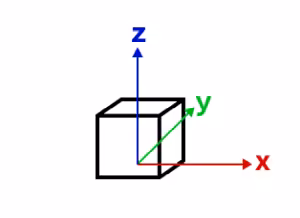
local vertex space
When a Mesh geometry with MeshLocalVertexSpace is displayed in a global scene and Mesh.spatialReference is WGS84, CGCS2000, or Web Mercator, the SDK places the local coordinate frame on the globe at MeshLocalVertexSpace.origin. The frame is aligned to the local tangent plane: X points east, Y points north, and Z points up. This is commonly called an east, north, up (ENU) frame.
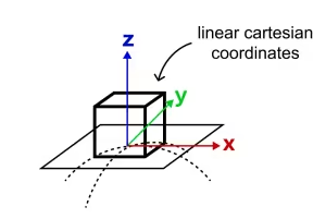
local vertex space aligned to the sphere's tangent plane at the origin point
This reference-frame approach is an approximation: it uses a spherical tangent plane matching how global scenes are rendered. The farther a vertex is from MeshLocalVertexSpace.origin, the more the local tangent plane diverges from the curved surface. This is usually acceptable for buildings and other models that occupy a limited area, but it is not appropriate for long objects that must follow the earth's curvature.
The word "local" in MeshLocalVertexSpace refers to coordinates from the source model measured from that model's own [0, 0, 0]. It does not mean that this vertex space is the right choice for a local view. For mesh graphics in a local view, use MeshGeoreferencedVertexSpace in the view's projected coordinate system.
Georeferenced vertex space
Mesh.vertexSpace gives meaning to the source x, y, z values stored in MeshVertexAttributes.position. A georeferenced vertex space interprets those numbers in relation to Mesh.spatialReference, either as offsets from a placement point or as absolute map coordinates.
- When the origin is set, the mesh's vertex coordinates are interpreted as offsets from that origin. This works well for 3D models created by CAD software whose x, y and z values are measured from the source model's own [0, 0, 0], and for those measured from a specific insertion point. The origin is the [x, y, z] coordinate, in the Mesh's spatialReference, where that local [0, 0, 0] or insertion point lands. The offset directions and units come from Mesh.spatialReference. In a projected coordinate system, these are usually map units such as meters.
- Without an origin, use this vertex space when the source x, y, z values are already absolute map coordinates, for example a mesh produced from a LiDAR scan, photogrammetry reconstruction, or surveyed surface and exported in a projected coordinate system. Each source position is used directly in Mesh.spatialReference.
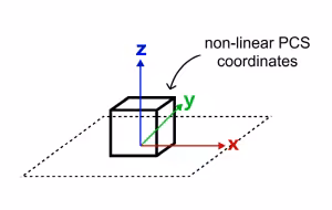
georeferenced vertex space on a projected coordinate system
A georeferenced vertex space is the usual choice for mesh graphics in local scenes. Use it when the view spatial reference is a projected coordinate system and Mesh.spatialReference uses the same projected coordinate system. In that configuration, the position values and the view use the same projected coordinate space, so display and editing can be efficient and predictable.
Do not use a georeferenced vertex space with a vertex space origin in WGS84 or CGCS2000 for source models whose x, y, z values are measured in meters. In those geographic coordinate systems, longitude and latitude are angular coordinates, so an offset such as [10, 0, 0] means ten degrees of longitude, not ten meters east. A building model can appear at the wrong size or far from the intended location. If the source model is measured in meters and should be placed on the globe, use MeshLocalVertexSpace instead.
Web Mercator
Web Mercator is a projected coordinate system, but it is treated specially in global scenes because of its central role in web mapping. A Mesh geometry whose Mesh.spatialReference is Web Mercator can use MeshLocalVertexSpace in a global SceneView. Other projected coordinate systems should use a local SceneView and MeshGeoreferencedVertexSpace.
Web Mercator is not recommended as the spatial reference for local scenes or for publishing 3D object layers that require accurate local dimensions. Web Mercator map units are distorted: one Web Mercator meter equals one ground meter only near the equator, and the scale variation increases with latitude. For local scenes and 3D object layer workflows, prefer a projected coordinate system designed for the area of interest.
Troubleshooting mesh georeferencing
If a mesh graphic is not displayed, or is displayed in the wrong place or at the wrong size, first check the browser console for warnings. Then narrow the problem in this order:
- Start with SceneView.viewingMode. In a global SceneView, the usual choice for model files whose positions are measured from the model's own [0, 0, 0] is MeshLocalVertexSpace. In a local SceneView, the usual choice is MeshGeoreferencedVertexSpace with a projected Mesh.spatialReference that matches SceneView.spatialReference.
- Identify what the source model's x, y, z values mean. They may be local model coordinates measured from [0, 0, 0], offsets from an insertion point, or absolute coordinates exported by a georeferenced workflow.
- Check the vertex space's origin when it has one. The origin should be the [x, y, z] coordinate where the source model's [0, 0, 0] or insertion point should land, using the coordinate system identified by Mesh.spatialReference.
- Check units. MeshLocalVertexSpace interprets position values as meters. MeshGeoreferencedVertexSpace with a vertex space origin interprets offsets in the units of Mesh.spatialReference.
Limitations
- MeshLocalVertexSpace is not supported for mesh graphics displayed in a local SceneView.
- Displaying or editing a Mesh geometry can be unsupported when Mesh.spatialReference, SceneView.spatialReference, and Mesh.vertexSpace would require costly or unavailable per-vertex projection.
- For 3D object feature editing workflows that use Mesh geometry, see the SceneLayer editing documentation and 3D object workflows in the SDK.
Create simple mesh geometry primitives
There are a couple of convenience functions in meshUtils to create simple primitive shapes. These shapes can help you get started with understanding mesh geometries.
// Create a box mesh geometrylet mesh = meshUtils.createBox(location, {  size: {    width: 100,    height: 50,    depth: 50  },  material: {    color: "red"  }});
// Create a graphic and add it to the viewlet graphic = new Graphic({  geometry: mesh,  symbol: {    type: "mesh-3d",    symbolLayers: [ { type: "fill" } ]  }});
view.graphics.add(graphic);
Create mesh geometries manually
Mesh geometries can be manually created by specifying vertexAttributes and components like in the following example:
// Create a mesh geometry representing a pyramidlet pyramidMesh = new Mesh({  vertexAttributes: {    // vertex positions for the Louvre pyramid, Paris    position: [      // vertex 0 - base of the pyramid, south      2.336006, 48.860818, 0,
      // vertex 1 - base of the pyramid, east      2.336172, 48.861114, 0,
      // vertex 2 - base of the pyramid, north      2.335724, 48.861229, 0,
      // vertex 3 - base of the pyramid, west      2.335563, 48.860922, 0,
      // vertex 4 - top of the pyramid      2.335896, 48.861024, 21    ]  },  // Add a single component with faces that index the vertices  // so we only need to define them once  components: [    {      faces: [        0, 4, 3,        0, 1, 4,        1, 2, 4,        2, 3, 4      ]    }  ],  // specify a spatial reference if the position of the vertices is not in WGS84});
// add the mesh geometry to a graphiclet graphic = new Graphic({  geometry: pyramidMesh,  symbol: {    type: "mesh-3d",    symbolLayers: [ { type: "fill" } ]  }});
view.graphics.add(graphic);
Note: Starting with version 4.11 autocasting is no longer supported for Mesh geometry.
Constructors
Constructor
Parameters
| Parameter | Type | Description | Required |
|---|---|---|---|
| properties | | |
Properties
| Property | Type | Class |
|---|---|---|
| readonly inherited | ||
| MeshComponent[] | null | undefined | | |
| readonly inherited | ||
| readonly | | |
| inherited | ||
| inherited | ||
| readonly inherited | ||
| readonly inherited | "not-loaded" | "loading" | "failed" | "loaded" | |
| readonly inherited | any[] | |
| readonly | | |
| inherited | ||
| | ||
| readonly | "mesh" | |
| | ||
| readonly | |
components
- Type
- MeshComponent[] | null | undefined
An array of mesh components that can be used to apply materials to different regions of the same mesh. There are three common usage patterns for components.
- Specify a material for the whole mesh. In this case, use a single
component with only a material (leaving faces as
null). - Reuse vertex attributes. When modeling continuous surfaces, it can be convenient to only specify vertices once and then simply refer to them. In this case, use a single component with faces set to index the vertex attributes that form triangles.
- Specify multiple materials for the same mesh. In this case, use multiple components with faces that determine to which region of the mesh the material of the component applies.
extent
- Type
- Extent
The 3D extent of the mesh geometry. The extent is computed from the vertex positions stored in the vertexAttributes. The 3D extent is computed on-demand and cached. If you modify the vertexAttributes manually, then you must call vertexAttributesChanged() to make sure the extent will be recomputed.
hasM
- Type
- boolean
Indicates if the geometry has m-values (measure). M-values allow attribute values to be stored with the geometry.
true: The geometry is m aware. M-values are part of the geometry coordinates.false: The geometry is not m aware. M-values are not part of the coordinates.
- Default value
- false
loadError
The Error object returned if an error occurred while loading.
loadStatus
- Type
- "not-loaded" | "loading" | "failed" | "loaded"
Represents the status of a load() operation.
| Value | Description |
|---|---|
| not-loaded | The object's resources have not loaded. |
| loading | The object's resources are currently loading. |
| loaded | The object's resources have loaded without errors. |
| failed | The object's resources failed to load. See loadError for more details. |
- Default value
- "not-loaded"
loadWarnings
- Type
- any[]
A list of warnings which occurred while loading.
origin
- Type
- Point
- Since
- ArcGIS Maps SDK for JavaScript 4.30
The origin of the mesh. This corresponds to the vertex space origin for relative vertex spaces. For absolute vertex spaces, the origin is at the bottom of the mesh.
spatialReference
- Type
- SpatialReference
The spatial reference of the geometry.
- Default value
- SpatialReference.WGS84 // wkid: 4326
transform
- Type
- MeshTransform | null | undefined
Additional local transformation of the mesh vertices. The transform is ignored if the vertexSpace is of type georeferenced and does not specify an MeshGeoreferencedVertexSpace.origin.
vertexAttributes
- Type
- MeshVertexAttributes
Object describing the attributes of each vertex of the mesh. Vertex attributes are flat numerical arrays that describe the position (mandatory), normal (used for lighting calculations and shading) and UV (used for mapping material images to the mesh surface) for each vertex.
Vertex attributes can be addressed by indices specified in the components MeshComponent.faces property. If the mesh does not contain any components, or if a component does not specify any faces, then the vertex attributes are interpreted as if each consecutive vertex triple makes up a triangle.
- Example
- let mesh = new Mesh({ spatialReference: SpatialReference.WebMercator });// Specify vertices for two triangles that make up a square// around a provided point. UV coordinates are set up to cover the square// from (0, 0) to (1, 1) from corner to corner.mesh.vertexAttributes = {position: [pt.x - 10, pt.y - 10, 100,pt.x + 10, pt.y - 10, 100,pt.x + 10, pt.y + 10, 100,pt.x - 10, pt.y - 10, 100,pt.x + 10, pt.y + 10, 100,pt.x - 10, pt.y + 10, 100],uv: [0, 0,1, 0,1, 1,0, 0,1, 1,0, 1]};
vertexSpace
- Type
- MeshVertexSpaceUnion
Defines how the SDK interprets the x, y, z position values stored in Mesh.vertexAttributes.position.
A source 3D model or custom vertex buffer usually stores positions as numbers, but those numbers do not indicate by themselves whether they are local model coordinates, offsets from a placement point, or absolute map coordinates. This property makes that interpretation explicit for the Mesh geometry.
Use MeshLocalVertexSpace when the position values are meter-based local model coordinates and should be placed in a global SceneView. Use MeshGeoreferencedVertexSpace when the position values should be interpreted as offsets or absolute coordinates in the coordinate system identified by Mesh.spatialReference, which is the usual choice for local scenes with a projected coordinate system.
This property is construct-only because changing it changes the meaning of every vertex position in the mesh. To change the vertex space of an existing mesh, use convertVertexSpace().
Methods
| Method | Signature | Class |
|---|---|---|
| deprecated static | createBox(location: Point, parameters?: CreateBoxParameters): Mesh | |
| deprecated static | createCylinder(location: Point, parameters?: CreateCylinderParameters): Mesh | |
| deprecated static | createFromGLTF(location: Point, url: string, parameters?: CreateFromGLTFParameters): Promise<Mesh> | |
| deprecated static | createFromPolygon(polygon: Polygon, parameters?: CreateFromPolygonParameters): Mesh | |
| deprecated static | createPlane(location: Point, parameters?: CreatePlaneParameters): Mesh | |
| deprecated static | createSphere(location: Point, parameters?: CreateSphereParameters): Mesh | |
| inherited static | fromJSON(json: any): any | |
| addComponent(component: MeshComponentProperties): void | | |
| inherited | cancelLoad(): this | |
| centerAt(location: Point, parameters?: CenterAtParameters): this | | |
| clone(): this | | |
| inherited | isFulfilled(): boolean | |
| inherited | isRejected(): boolean | |
| inherited | isResolved(): boolean | |
| inherited | load(options?: AbortOptions | null | undefined): Promise<this> | |
| offset(dx: number, dy: number, dz: number): this | | |
| removeComponent(component: MeshComponent): void | | |
| rotate(angleX: number, angleY: number, angleZ: number, parameters?: RotateParameters): this | | |
| scale(factor: number, parameters?: ScaleParameters): this | | |
| toBinaryGLTF(options?: ExportGLTFOptions): Promise<ArrayBuffer> | | |
| inherited | toJSON(): any | |
| vertexAttributesChanged(): void | | |
| inherited | when<TResult1 = this, TResult2 = never>(onFulfilled?: OnFulfilledCallback<this, TResult1> | null | undefined, onRejected?: OnRejectedCallback<TResult2> | null | undefined): Promise<TResult1 | TResult2> |
createBox
- Signature
-
createBox (location: Point, parameters?: CreateBoxParameters): Mesh
Creates a mesh representing a box. The spatial reference of the resulting mesh is the same as the location where it is placed.
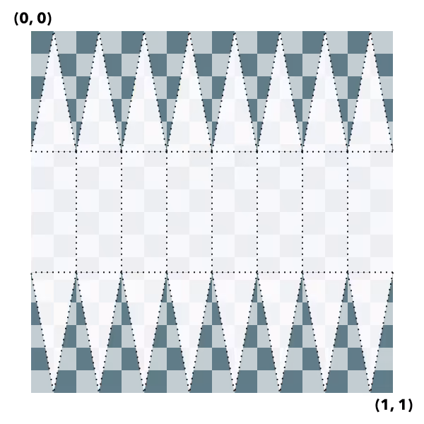
Box UV coordinate space
The box geometry will have UV coordinates generated according to the following scheme:
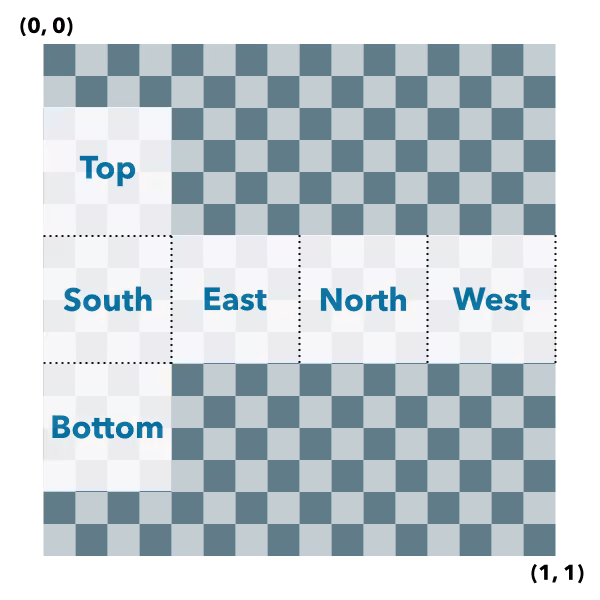
Parameters
| Parameter | Type | Description | Required |
|---|---|---|---|
| location | The location bottom center of the box. | | |
| parameters | Parameters to configure the box creation. | |
- Returns
- Mesh
The resulting mesh.
- Examples
- let mesh = Mesh.createBox(point, {size: {width: 10,height: 100,depth: 20},material: {color: "green"}});let mesh = Mesh.createBox(point, {imageFace: "top",material: {colorTexture: new MeshTexture({ url: "./url-to-image.png" })}});
createCylinder
- Signature
-
createCylinder (location: Point, parameters?: CreateCylinderParameters): Mesh
Creates a mesh representing a cylinder. The spatial reference of the resulting mesh is the same as the location where it is placed.
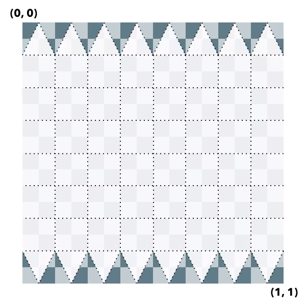
Cylinder UV coordinate space
The cylinder geometry will have UV coordinates generated according to the following scheme (example is shown for 8 vertices cylinder):
Parameters
| Parameter | Type | Description | Required |
|---|---|---|---|
| location | The location of the bottom center of the cylinder. | | |
| parameters | Parameters to configure the cylinder creation. | |
- Returns
- Mesh
The resulting mesh.
createFromGLTF
- Signature
-
createFromGLTF (location: Point, url: string, parameters?: CreateFromGLTFParameters): Promise<Mesh>
- Since
- ArcGIS Maps SDK for JavaScript 4.11
Creates a new mesh geometry from a glTF model referenced by the url parameter.
The spatial reference of the resulting mesh is the same as the spatial reference of the location parameter. For
more information on the supported glTF features you can read the
Visualizing points with 3D symbols guide topic. Animations are currently unsupported.
Parameters
| Parameter | Type | Description | Required |
|---|---|---|---|
| location | The location of the origin of the model. If the location does not
contain a z-value, z is assumed to be | | |
| url | The URL of the glTF model. The URL should point to a glTF file (.gltf or .glb) which can reference additional binary (.bin) and image files (.jpg, .png). | | |
| parameters | Parameters to configure the mesh from glTF creation. | |
createFromPolygon
- Signature
-
createFromPolygon (polygon: Polygon, parameters?: CreateFromPolygonParameters): Mesh
Creates a new mesh geometry from a polygon geometry. The resulting mesh contains only
a position vertex attribute and a single component with faces. The default shading will be
set to flat. The spatial reference of the resulting mesh is the same
as the input polygon. The resulting mesh will not contain any UV nor normal vertex attributes.
Parameters
| Parameter | Type | Description | Required |
|---|---|---|---|
| polygon | The input polygon. | | |
| parameters | Optional parameters. | |
- Returns
- Mesh
A new mesh representing the triangulated polygon.
createPlane
- Signature
-
createPlane (location: Point, parameters?: CreatePlaneParameters): Mesh
Creates a mesh representing a plane. The spatial reference of the resulting mesh is the same as the location where it is placed. A plane consists of two triangles and may be conveniently oriented at creation time.
Plane UV coordinate space
The plane geometry will have UV coordinates generated according to the following scheme:

Parameters
| Parameter | Type | Description | Required |
|---|---|---|---|
| location | The location of the bottom center of the plane. | | |
| parameters | Parameters to configure the plane creation. | |
- Returns
- Mesh
The resulting mesh.
createSphere
- Signature
-
createSphere (location: Point, parameters?: CreateSphereParameters): Mesh
Creates a mesh representing a sphere. The spatial reference of the resulting mesh is the same as the location where it is placed.
Sphere UV coordinate space
The sphere geometry will have UV coordinates generated according to the following scheme (example is shown for 8x8 vertices sphere):
Parameters
| Parameter | Type | Description | Required |
|---|---|---|---|
| location | The location of the bottom center of the sphere. | | |
| parameters | Parameters to configure the sphere creation. | |
- Returns
- Mesh
The resulting mesh.
fromJSON
- Signature
-
fromJSON (json: any): any
Creates a new instance of this class and initializes it with values from a JSON object
generated from an ArcGIS product. The object passed into the input json
parameter often comes from a response to a query operation in the REST API or a
toJSON()
method from another ArcGIS product. See the Using fromJSON()
topic in the Guide for details and examples of when and how to use this function.
Parameters
| Parameter | Type | Description | Required |
|---|---|---|---|
| json | A JSON representation of the instance in the ArcGIS format. See the ArcGIS REST API documentation for examples of the structure of various input JSON objects. | |
- Returns
- any
Returns a new instance of this class.
addComponent
- Signature
-
addComponent (component: MeshComponentProperties): void
Adds a component to the mesh.
Parameters
| Parameter | Type | Description | Required |
|---|---|---|---|
| component | The component to add. | |
- Returns
- void
cancelLoad
- Signature
-
cancelLoad (): this
Cancels a load() operation if it is already in progress.
- Returns
- this
centerAt
- Signature
-
centerAt (location: Point, parameters?: CenterAtParameters): this
Centers the mesh at the specified location without changing its scale. This effectively adjusts the mesh origin and mesh vertices such that vertices are given relative to the new location and the new location is the new origin. The effective georeferenced vertex positions will not change.
The mesh will be modified in place. To modify a copy of the mesh instead, use clone() before calling centerAt().
Parameters
| Parameter | Type | Description | Required |
|---|---|---|---|
| location | The location at which to center the mesh. | | |
| parameters | Additional parameters. | |
- Returns
- this
The modified mesh.
clone
- Signature
-
clone (): this
Creates a deep clone of the Mesh object.
- Returns
- this
A new instance of a Mesh object equal to the object used to call
.clone().
isFulfilled
- Signature
-
isFulfilled (): boolean
isFulfilled() may be used to verify if creating an instance of the class is fulfilled (either resolved or rejected).
If it is fulfilled, true will be returned.
- Returns
- boolean
Indicates whether creating an instance of the class has been fulfilled (either resolved or rejected).
isRejected
- Signature
-
isRejected (): boolean
isRejected() may be used to verify if creating an instance of the class is rejected.
If it is rejected, true will be returned.
- Returns
- boolean
Indicates whether creating an instance of the class has been rejected.
isResolved
- Signature
-
isResolved (): boolean
isResolved() may be used to verify if creating an instance of the class is resolved.
If it is resolved, true will be returned.
- Returns
- boolean
Indicates whether creating an instance of the class has been resolved.
load
- Signature
-
load (options?: AbortOptions | null | undefined): Promise<this>
Loads the resources referenced by this class. This method automatically executes for a View and all of the resources it references in Map if the view is constructed with a map instance.
This method must be called by the developer when accessing a resource that will not be loaded in a View.
The load() method only triggers the loading of the resource the first time it is called. The subsequent calls return the same promise.
It's possible to provide a signal to stop being interested into a Loadable instance load status.
When the signal is aborted, the instance does not stop its loading process, only cancelLoad() can abort it.
offset
- Signature
-
offset (dx: number, dy: number, dz: number): this
Offsets the mesh geometry by the specified distance in x, y, and z. The units of x, y, and z are the units of the spatial reference. When the vertex space is local or georeferenced with an origin, the offset is applied to the origin of the vertex space. When the vertex space is georeferenced without origin, the offset is applied to the vertex positions directly.
The mesh will be modified in place. To modify a copy of the mesh instead, use clone() before calling offset().
removeComponent
- Signature
-
removeComponent (component: MeshComponent): void
Removes a component from the mesh.
Parameters
| Parameter | Type | Description | Required |
|---|---|---|---|
| component | The component to remove. | |
- Returns
- void
rotate
- Signature
-
rotate (angleX: number, angleY: number, angleZ: number, parameters?: RotateParameters): this
Rotates the mesh geometry around its x, y and z axis (in that order). For each rotation angle, the rotation direction is clockwise when looking in the direction of the respective axis. The mesh will be modified in place. To modify a copy of the mesh instead, use clone() before calling rotate().
Parameters
| Parameter | Type | Description | Required |
|---|---|---|---|
| angleX | The angle by which to rotate around the x-axis (in degrees). | | |
| angleY | The angle by which to rotate around the y-axis (in degrees). | | |
| angleZ | The angle by which to rotate around the z-axis (in degrees). | | |
| parameters | Additional parameters. | |
- Returns
- this
The modified mesh (this instance).
- Example
- // rotate the mesh in the horizontal plane (around the z axis) by 90 degrees and tilt it in the lateral// vertical plane (around the y axis) by 20 degrees.mesh.rotate(0, 20, 90);
scale
- Signature
-
scale (factor: number, parameters?: ScaleParameters): this
Scales the mesh geometry by the specified factor. The mesh will be modified in place. To modify a copy of the mesh instead, use clone() before calling scale().
Parameters
| Parameter | Type | Description | Required |
|---|---|---|---|
| factor | The amount to scale the geometry. | | |
| parameters | Additional parameters. | |
- Returns
- this
The modified mesh (this instance).
toBinaryGLTF
- Signature
-
toBinaryGLTF (options?: ExportGLTFOptions): Promise<ArrayBuffer>
- Since
- ArcGIS Maps SDK for JavaScript 4.30
Export a mesh to a binary glTF (glb) representation. The resulting ArrayBuffer could be uploaded to a service or give an application the option to download a representation of the mesh.
Parameters
| Parameter | Type | Description | Required |
|---|---|---|---|
| options | Additional options. | |
- Returns
- Promise<ArrayBuffer>
The binary glTF data.
- Example
- function downloadBufferAsFile(filename, buffer, type) {const objectUrl = URL.createObjectURL(new Blob([buffer], { type }));const a = document.createElement("a");a.download = filename;a.href = objectUrl;a.style.display = "none";document.body.appendChild(a);a.click();document.body.removeChild(a);URL.revokeObjectURL(objectUrl);}const buffer = await mesh.toBinaryGLTF();downloadBufferAsFile("model.glb", buffer, "model/gltf-binary");
toJSON
- Signature
-
toJSON (): any
Converts an instance of this class to its ArcGIS portal JSON representation. See the Using fromJSON() guide topic for more information.
- Returns
- any
The ArcGIS portal JSON representation of an instance of this class.
vertexAttributesChanged
- Signature
-
vertexAttributesChanged (): void
Notifies that any cached values that depend on vertex attributes need to be recalculated. Use this method after modifying the vertex attributes in place so that values that depend on them (such as the calculation of the extent) are recalculated accordingly.
- Returns
- void
when
- Signature
-
when <TResult1 = this, TResult2 = never>(onFulfilled?: OnFulfilledCallback<this, TResult1> | null | undefined, onRejected?: OnRejectedCallback<TResult2> | null | undefined): Promise<TResult1 | TResult2>
when() may be leveraged once an instance of the class is created. This method takes two input parameters: an onFulfilled function and an onRejected function.
The onFulfilled executes when the instance of the class loads. The
onRejected executes if the instance of the class fails to load.
Parameters
| Parameter | Type | Description | Required |
|---|---|---|---|
| onFulfilled | OnFulfilledCallback<this, TResult1> | null | undefined | The function to call when the promise resolves. | |
| onRejected | The function to execute when the promise fails. | |
- Returns
- Promise<TResult1 | TResult2>
Returns a new promise for the result of
onFulfilledthat may be used to chain additional functions.
- Example
- // Although this example uses MapView, any class instance that is a promise may use when() in the same waylet view = new MapView();view.when(function(){// This function will execute once the promise is resolved}, function(error){// This function will execute if the promise is rejected due to an error});