This sample demonstrates how to place arrows along a line using CIMSymbols to visualize the direction of one-way streets in Redlands. CIMSymbols are used to display multi-layer vector symbols, and can allow for custom symbols and visualizations in your layer. See the CIM specification for more information.
How it works
A UniqueValueRenderer is used to create the visualization for this layer. If the street is a one-way street, a CIMSymbol of a black line with arrows is created to visualize the movement of traffic on that street. If the street is not one-way, a default SimpleLineSymbol is used.
renderer: { type: "unique-value", // autocasts as UniqueValueRenderer field: "oneway", defaultSymbol: { type: "simple-line" // default SimpleLineSymbol }, uniqueValueInfos: [{ value: "yes", // when one-way='yes', create CIMSymbol line with arrows label: "One-way street", symbol: { type: "cim", // autocasts as CIMSymbol data: { type: "CIMSymbolReference", symbol: { type: "CIMLineSymbol", symbolLayers: [{ // black 1px line symbol type: "CIMSolidStroke", enable: true, width: 1, color: [0, 0, 0, 255] }, { // arrow symbol type: "CIMVectorMarker", enable: true, size: 5, markerPlacement: { type: "CIMMarkerPlacementAlongLineSameSize", // places same size markers along the line endings: "WithMarkers", placementTemplate: [19.5], // determines space between each arrow angleToLine: true // symbol will maintain its angle to the line when map is rotated }, frame: { xmin: -5, ymin: -5, xmax: 5, ymax: 5 }, markerGraphics: [{ type: "CIMMarkerGraphic", geometry: { rings: [ [ [-8, -5.47], [-8, 5.6], [1.96, -0.03], [-8, -5.47] ] ] }, symbol: { // black fill for the arrow symbol type: "CIMPolygonSymbol", symbolLayers: [{ type: "CIMSolidFill", enable: true, color: [0, 0, 0, 255] }] } }] }] } } } }]}CIM line symbols are not currently supported in 3D Scenes. Additionally, not everything listed in the CIM specification is currently supported.
Click here for more information on CIMSymbol limitations.
Related samples and resources
Intro to CIMSymbol
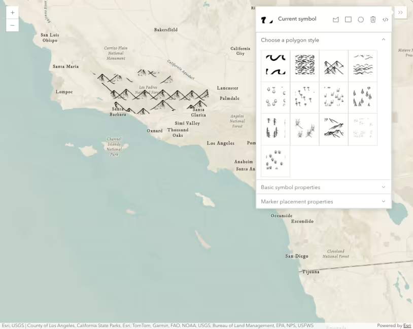
CIMSymbol lines and polygons