Important notes:
- This sample shows experimental functionality, please read the documentation carefully before using it in a product.
- This sample is written for expert developers familiar with WebGL and hardware-accelerated rendering.
This sample demonstrates how to implement an animated trail (or flow) effect for polyline graphics. This description assumes familiarity with WebGL and custom WebGL layer views. It’s similar to the Custom WebGL layer view sample, which triangulates points into quads. This sample instead uses polyline triangulation.
The updatePositions() method has been modified to convert the geometry of polyline graphics into triangle meshes. Special per-vertex attributes are computed and stored on the GPU and then used in conjunction with per-frame uniform values to implement an efficient animation system that can support thousands of trails at the same time.
In this sample we tessellated polylines using custom code; version 4.14 of the ArcGIS API introduces generic tessellation routines that the developer can use to tessellate arbitrary geometries; see the SDK tessellation sample for more details.
Creating the mesh
WebGL draw calls operate on geometric primitives. While in WebGL there is support for the gl.LINES primitive, this is not very flexible and cannot be used to implement advanced effects such as the one showcased in this sample. The most flexible primitive is the indexed triangle list, which can be rendered using gl.drawElements(gl.TRIANGLES, ...). The sample application renders all polylines in the view using one single such call. To feed the rasterization we need to set up appropriate vertex attributes and an index buffer.
Triangulating lines
A polyline can be represented using triangles. A simple triangulation scheme is the one in which every vertex of the original polyline is extruded into two GPU vertices in opposite directions. Groups of four GPU vertices are then connected using two triangles for a total of six indices.
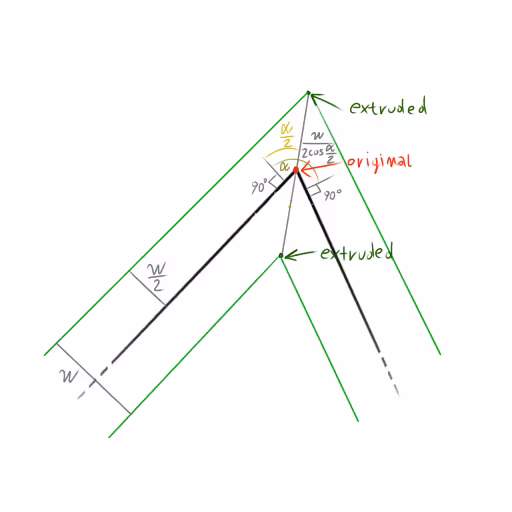
The geometry of the extrusion is exemplified by the figure below. Let α be the angle of a turn, and w the width of the polyline on screen, in pixels. The extrusion direction forms an angle of α / 2 with each of the normals to the segments; the amount of the extrusion is w / (2 cos(α / 2)).
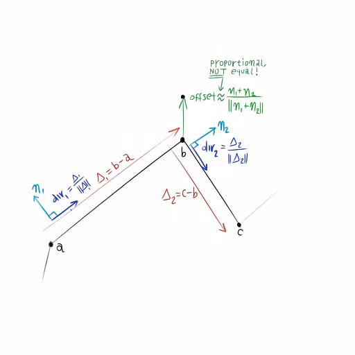
We use vector algebra to study vertex extrusion. Let’s consider three consecutive vertices a, b and c of a polyline and suppose that we want to compute the offset vector that drives the extrusion of point b. Let’s consider segments ab and bcseparately. We compute the vector that goes from a to b as Δ1 = b - a; let (dx, dy) = Δ1 / ||Δ1|| be the normalized vector that expresses the direction of segment ab; then n1 = (-dy, dx) is the normal to the segment. Normal n2 can be computed in the same way for segment bc. The direction of the offset vector can then be computed as the normalized average ofn1 and n2, i.e. offsetDir = (n1 + n2) / ||n1 + n2||.
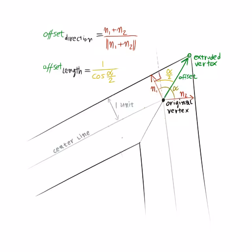
We have characterized the direction of the extrusion, but not its amount; intuitively, a sharp turn should result in a larger extrusion than a shallow one; also, we should extrude more if we want the polyline to appear thicker. Let’s normalize the width of the polyline to 2 so that its edges just touch the tips of the normal vectors. Consider the right triangle that has n1 (or n2) and offset as sides. It is easy to see that offset cos(α / 2) must equal 1 because the normal is unit length; from this we can conclude the length of the offset vector is exactly 1 / cos(α / 2). For a polyline of width w we have to scale the offset by a factor ofw / 2, which leads to the w / (2 cos(α / 2)) factor we introduced at the beginning of this section.
Each polyline graphic is processed once, and the extrusion information is captured in attributes stored in a vertex buffer. The extruded vertices are connected into triangles using an index buffer. These generated buffers drive the rasterization process and do not need to be regenerated at each frame. We regenerate them only when the view becomes stationary to account for the limited precision of floating-point numbers on GPUs. See Custom WebGL layer view for a discussion of this technique.
Vertex format
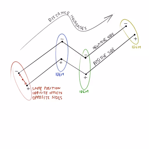
Each vertex of the original polyline results in two GPU vertices. These have a position attribute, which is the same as the vertex they originate from and use the same units of the spatial reference. GPU vertices also have an offset attribute, which is a unit vector that points toward the extruded GPU vertex. The two offset vectors in a pair are opposite of each other. Note that we store _normalized_offset vectors. These are the offsets that would make a polyline appear having width equal to 2 pixels. The vertex shader is responsible for scaling the offset attribute so the polyline renders thicker.
To apply a texture to the line, we need to build a UV space on it. This requires two new attributes:
- distance - Defines a coordinate that increases along the line. It is measured in the spatial reference units and starts a 0 on the first vertex and increases with each polyline segment.
- side - This is set to
+1or-1depending on the edge of the extruded polyline the GPU vertex belongs to.
We want every line to be of a different color. We could use a uniform to store the color, but this would prevent us from drawing all lines using a single call. Therefore, we encode the color as a 32-bit RGBA attribute.
The triangulation algorithm
The polyline triangulation algorithm is implemented in the updatePositions() method and assumes that all graphics stored on the layer have polyline geometries.
We start by counting the number of vertices and indices required, which we do by iterating on all graphics. For simplicity, we only triangulate the first path of each graphic. A polyline with N vertices has N - 1 segments. For each vertex we need 2GPU vertices extruded in opposite directions. For each segment we need two triangles (i.e. 6 indices).
let vtxCount = 0;let idxCount = 0;
for (let i = 0; i < graphics.items.length; ++i) { const graphic = graphics.items[i]; const path = graphic.geometry.paths[0];
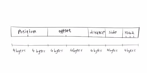
vtxCount += path.length * 2; idxCount += (path.length - 1) * 6;}We allocate an ArrayBuffer that has enough space for vtxCount vertices. Every vertex has 6 floating-point values and a 4 bytes color, so we need a total of 7 * vtxCount * 4 bytes. We create two views to this area of memory; one is used to write floating-point values, and the other is used to write colors. We also allocate the index memory and contextually create an unsigned short view to it.
const vertexData = new ArrayBuffer(7 * vtxCount * 4);const floatData = new Float32Array(vertexData);const colorData = new Uint8Array(vertexData);const indexData = new Uint16Array(idxCount);Then we start computing and writing the vertex attributes. Writing to vertex and index memory happens at the locations pointed by two cursors, starting at zero.
let vtxCursor = 0;let idxCursor = 0;Then we iterate on all graphics, considering only the first path of each graphic. For each path we need to run the triangulation algorithm. We start by initializing a variable s with an empty triangulation state, {}; this state will be mutated as the individual points that form a path are processed. Every time that we finish processing a graphic, we reset the state s to {} before we process the next one.
let s = {};
for (let j = 0; j < path.length; ++j) {  const p = path[j];
  // ...here we process p...}
To process the current vertex p we first check the state s. If this is not the first iteration for this path, we’ll already have the s.current vertex and use it to compute the deltaas p - s.current. Then we compute the length of the segment as the norm of delta (the normalized delta is the direction of the segment). By rotating this direction by 90° we obtain the normal to the segment.
s.delta = [p[0] - s.current[0], p[1] - s.current[1]];const deltaLength = Math.sqrt(s.delta[0] * s.delta[0] + s.delta[1] * s.delta[1]);s.direction = [s.delta[0] / deltaLength, s.delta[1] / deltaLength];const normal = [-s.direction[1], s.direction[0]];For the first and last vertex of the polyline, the segment normal is the offset vector that determines the extrusion. For all other intermediate vertices, the normals of the two segments that share a vertex must be averaged, normalized, and scaled by the inverse of the cosine of half the angle between the normals. This can be computed as the dot product between a segment normal and the normalized (but still unscaled) offset. The previous segment normal is retrieved from the triangulation state as s.normal.
s.offset = [s.normal[0] + normal[0], s.normal[1] + normal[1]];const offsetLength = Math.sqrt(s.offset[0] * s.offset[0] + s.offset[1] * s.offset[1]);s.offset[0] /= offsetLength;s.offset[1] /= offsetLength;const d = s.normal[0] * s.offset[0] + s.normal[1] * s.offset[1];s.offset[0] /= d;s.offset[1] /= d;The computed values are then written to attribute buffers. We use the floating-point view to write position, offset, distance and side, and we use the unsigned byte view to write the color.
floatData[vtxCursor * 7 + 0] = s.current[0] - this.centerAtLastUpdate[0];floatData[vtxCursor * 7 + 1] = s.current[1] - this.centerAtLastUpdate[1];floatData[vtxCursor * 7 + 2] = s.offset[0];floatData[vtxCursor * 7 + 3] = s.offset[1];floatData[vtxCursor * 7 + 4] = s.distance;floatData[vtxCursor * 7 + 5] = +1;colorData[4 * (vtxCursor * 7 + 6) + 0] = color[0];colorData[4 * (vtxCursor * 7 + 6) + 1] = color[1];colorData[4 * (vtxCursor * 7 + 6) + 2] = color[2];colorData[4 * (vtxCursor * 7 + 6) + 3] = 255;floatData[vtxCursor * 7 + 7] = s.current[0] - this.centerAtLastUpdate[0];floatData[vtxCursor * 7 + 8] = s.current[1] - this.centerAtLastUpdate[1];floatData[vtxCursor * 7 + 9] = -s.offset[0];floatData[vtxCursor * 7 + 10] = -s.offset[1];floatData[vtxCursor * 7 + 11] = s.distance;floatData[vtxCursor * 7 + 12] = -1;colorData[4 * (vtxCursor * 7 + 13) + 0] = color[0];colorData[4 * (vtxCursor * 7 + 13) + 1] = color[1];colorData[4 * (vtxCursor * 7 + 13) + 2] = color[2];colorData[4 * (vtxCursor * 7 + 13) + 3] = 255;vtxCursor += 2;After we have emitted at least four vertices, we can start emitting indices. At every iteration we emit six indices - two triangles connecting the two extruded GPU vertices just computed to the ones that were computed in the previous iteration.
indexData[idxCursor + 0] = vtxCursor - 4;indexData[idxCursor + 1] = vtxCursor - 3;indexData[idxCursor + 2] = vtxCursor - 2;indexData[idxCursor + 3] = vtxCursor - 3;indexData[idxCursor + 4] = vtxCursor - 1;indexData[idxCursor + 5] = vtxCursor - 2;idxCursor += 6;Before continuing on to the next iteration, we need to make the latest point, the latest computed normal, the current ones, and increment the distance by the length of the segment that was processed by this iteration.
s.normal = normal;s.distance += deltaLength;s.current = p;There are two special cases that we have only briefly mentioned:
- The offset of the first vertex is equal to the first computed normal (i.e.
const normal = [-s.direction[1], s.direction[0]]) because there is no previous normal to average it. - Conversely, the offset of the last vertex is equal to the last normal computed when processing the last segment and is recovered by the state (i.e.
s.normal).
To help you understand the triangulation logic, we prepared a pen that showcases the inner working of the algorithm in the context of a simple Canvas2D app.
Creating the trail effect using shaders
In the present section we briefly discuss the vertex and fragment shader that implement the colored trail effect.
Vertex shader
The original vertex is transformed by the transform matrix, which is determined by map center, scale, and rotation. Then the vertex is extruded by adding the offset vector scaled and rotated by the extrude matrix, which includes a half line width factor but is insensitive to map scale so that lines do not get larger as the view is zoomed in. Finally, the extruded vector is transformed by the display matrix, which is determined by the size of the viewport. The distance, side, and color attributes are passed unchanged to the fragment shader.
The interpolator will cause the fragments (v_distance, v_side) pair to vary smoothly so that v_side equals 0 on the centerline while v_distanceis 0 at one end of the polyline and equals the length of the polyline in map units at the other end.
uniform mat3 u_transform;uniform mat3 u_extrude;uniform mat3 u_display;
attribute vec2 a_position;attribute vec2 a_offset;attribute float a_distance;attribute float a_side;attribute vec4 a_color;
varying float v_distance;varying float v_side;varying vec4 v_color;
void main(void) {  gl_Position.xy = (u_display * (u_transform * vec3(a_position, 1.0) + u_extrude * vec3(a_offset, 0.0))).xy;  gl_Position.zw = vec2(0.0, 1.0);  v_distance = a_distance;  v_side = a_side;  v_color = a_color;}
Fragment shader
The fragment shader computes two opacity factors, a1 and a2, based on the position of the fragment along and _across_the line respectively. This information is captured by the interpolated (v_distance, v_side) pair as detailed in the previous paragraph. Factor a1 is dependent on the current time and the distance associated to the current fragment, while a2 is such that the line is more opaque near the centerline and more transparent near the edges. We use a modoperation so that the trails repeat spatially along each line, and each line never runs out of trails to display.
uniform float u_current_time;
varying float v_distance;varying float v_side;varying vec4 v_color;
const float TRAIL_SPEED = 50.0;const float TRAIL_LENGTH = 300.0;const float TRAIL_CYCLE = 1000.0;
void main(void) {  float d = mod(v_distance - u_current_time * TRAIL_SPEED, TRAIL_CYCLE);  float a1 = d < TRAIL_LENGTH ? mix(0.0, 1.0, d / TRAIL_LENGTH) : 0.0;  float a2 = exp(-abs(v_side) * 3.0);  float a = a1 * a2;  gl_FragColor = v_color * a;}