Important notes:
- This sample shows experimental functionality, please read the documentation carefully before using it in a product.
- This sample targets expert developers familiar with WebGL and hardware-accelerated rendering.
This sample demonstrates how to render graphics using a custom WebGL layer view. It can be used as the starting point for complex visualizations where the developer has full control of the rendering process.
This description assumes familiarity with WebGL and custom WebGL layer views. It is similar to the Custom WebGL layer view sample, which triangulates points into quads. This sample instead uses the new tessellate*() methods implemented by BaseLayerViewGL2D. These helpers methods allow the developer to create triangle meshes for any geometry type, including polylines and polygons.
The updatePositions() method in the original sample has been modified to convert the geometry of any graphic into triangle meshes; these meshes have special per-vertex attributes that the shader program uses to render any geometry type.
Listening for changes
The custom layer is a subclass of GraphicsLayer. Every time that the graphics change, the layerview will reprocess all the graphics and recreate all the meshes. In the attach() method of the custom layer view a listener is set up that will fire for any change to the graphic collection; when a change is detected all the graphics are reprocessed using the custom method this.processGraphic(); each call to this.processGraphic() creates a promise that resolves when the mesh for that graphic has been created. When done, all the meshes are saved to themeshes member variable and the entire layer view is marked as dirty by setting needsUpdate to true, meaning the collection of meshes has changed but they have not been uploaded to the GPU for rendering.
    const CustomLayerView2D = BaseLayerViewGL2D.createSubclass({
      attach() {        const gl = this.context;
        // We listen for changes to the graphics collection of the layer        // and trigger the generation of new frames. A frame rendered while        // `needsUpdate` is true may cause an update of the vertex and        // index buffers.        const requestUpdate = () => {          // Tessellate graphics.          this.promises = [];          this.layer.graphics.forEach(this.processGraphic.bind(this));          Promise.all(this.promises).then((meshes) => {            this.meshes = meshes;            this.needsUpdate = true;            this.requestRender();          });        };
        this.watcher = reactiveUtils.watch(              () => this.layer.graphics,              requestUpdate,              {                initial: true              }            );
        ...    }
Processing the graphics
Each graphic is converted to a mesh by a call to processGraphic(). The geometry type determines whichtessellate*() method is called to create the mesh. In the following code snippets we focus on the polyline case, but the other cases are analogous.
Attributes from the graphic can be used to drive the values of the other parameters of the tessellate*()method of choice. For instance a width attribute of the graphics can be passed as the width parameter oftessellatePolyline() method. Note that the width parameter is a pure number, and the tessellatePolyline()method does not make any assumption with regard to the units being used; from now on, we will assume thatwidth is in pixels, but a better option would be using points or some other screen-space length unit.
Each graphic becomes a promise in the this.promises array; each promise resolves to an object that contains the resulting mesh as well as the attribute and symbol objects of the original graphic, effectively binding together the mesh and all the information that may determine its appearance on screen.
processGraphic(g) { switch (g.geometry.type) { case "extent": // Call this.tessellateExtent()... break; case "point": // Call this.tessellatePoint()... break; case "multipoint": // Call this.tessellateMultipoint()... break; case "polyline": this.promises.push( this.tessellatePolyline( g.geometry, (g.attributes && g.attributes.width != null) ? g.attributes.width : 20 ).then((mesh) => { return { mesh: mesh, attributes: g.attributes }; }) ); break; case "polygon": // Call this.tessellatePolygon()... break; } }Writing the vertex and index buffers
The updatePositions() method is called every time that the graphics collection is modified or when the view becomes stationary again after a change to the viewpoint; see the animated markers sample for more details about the updatePositions() method and handling of view changes.
The updatePositions() method is responsible for writing the mesh data to the vertex and array buffers. Each of the seven vertex attributes is encoded as a floating point value; one last GPU attribute a_upright is taken from theupright attribute of the graphic, if present; it is true for markers that should not rotate with the map.
Your app may not need some of the GPU attributes that we use here, or it could even introduce additional ones and define arbitrary mappings between the graphic’s attributes and symbol properties and what gets written to the buffers.
    updatePositions(renderParameters) {      ...      for (let meshIndex = 0; meshIndex < this.meshes.length; ++meshIndex) {        ...        const upright = (item.attributes && item.attributes.upright) ? 1 : 0;        ...        for (let i = 0; i < mesh.vertices.length; ++i) {          let v = mesh.vertices[i];          vertexData[currentVertex * 8 + 0] = v.x - this.centerAtLastUpdate[0];          vertexData[currentVertex * 8 + 1] = v.y - this.centerAtLastUpdate[1];          vertexData[currentVertex * 8 + 2] = v.xOffset;          vertexData[currentVertex * 8 + 3] = v.yOffset;          vertexData[currentVertex * 8 + 4] = v.uTexcoord;          vertexData[currentVertex * 8 + 5] = v.vTexcoord;          vertexData[currentVertex * 8 + 6] = v.distance;          vertexData[currentVertex * 8 + 7] = upright;          currentVertex++;        }      }
      gl.bindBuffer(gl.ARRAY_BUFFER, this.vertexBuffer);      gl.bufferData(gl.ARRAY_BUFFER, vertexData, gl.STATIC_DRAW);      gl.bindBuffer(gl.ELEMENT_ARRAY_BUFFER, this.indexBuffer);      gl.bufferData(gl.ELEMENT_ARRAY_BUFFER, indexData, gl.STATIC_DRAW);      ...    }
Vertex layout specification
The vertex specification used by this sample is very simple but fairly flexible, and enables rendering of all geometry types using a single shader program. There are five geometry types.
- Polygon is a 2-dimensional geometry type; they are made up of vertices, organized in rings; each vertex is expressed in map units; each of the original vertices is fed to the GPU as a single vertex with the same geographic position, stored in the
a_positionattribute. - Extent is treated as the polygon type.
- Polyline is a 1-dimensional geometry type; for each line vertex, 2 distinct GPU vertices are created; they have the same
a_positionattribute, but have opposinga_offsetvectors that enable extrusion and give the polyline its thickness. - Point is a 0-dimensional geometry type; for each point, 4 distinct GPU vertices are created; all share the same
a_positionattribute, but have differenta_offsetvectors that enable extrusion into quad in screen-space. - Multipoint is treated as the point type.
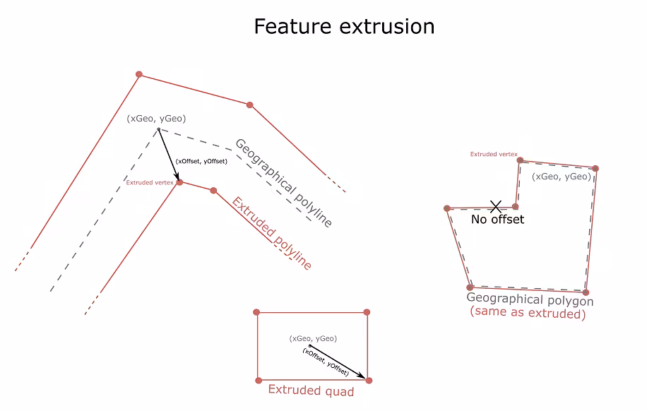
Splitting positional info over two attributes a_position and a_offset is crucial to implement the anti-rotation and anti-zoom behavior that the user expects from certain symbology. For instance, lines exhibit anti-zoom behavior in the sense that they do not become thicker as the user zooms in; furthermore, markers and labels also exhibit anti-zoom behavior, as their size does not change as the user zooms in; additionally, they often also exhibit anti-rotation behavior: they stay upright as the user rotates the map.
For more information on symbol extrusion and anti-rotation and anti-zoom behavior, see the animated markers and animated lines samples.
Shading
Let us now discuss the vertex shader.
    precision highp float;
    uniform mat3 u_transform;    uniform mat3 u_rotation;    uniform mat3 u_display;
    attribute vec2 a_position;    attribute vec2 a_offset;    attribute vec2 a_texcoord;    attribute float a_distance;    attribute float a_upright;
    varying vec2 v_texcoord;
    void main(void) {        vec3 transformedOffset = mix(u_rotation * vec3(a_offset, 0.0), vec3(a_offset, 0.0), a_upright);        gl_Position.xy = (u_display * (u_transform * vec3(a_position, 1.0) + transformedOffset)).xy;        gl_Position.zw = vec2(0.0, 1.0);        v_texcoord = a_texcoord;    }
The only responsibility of the vertex shader is the computation of vertex position; since the scene is 2D, components z and w are set to 0 and 1 respectively.The computation of x and y conceptually takes place in 4 steps.
- The first step is the rotation of the offset vector to account for map rotation, which is encoded in the
u_rotationmatrix; we do it only ifa_uprightis0. Instead of branching using anif (...)statement, we usea_uprighttomix()between the rotated and the stationary version of the offset vectors. - Then we transform the geographic position
a_positionusing theu_transformmatrix, which converts from map units to pixels. - The third step is adding the (possibly rotated) offset vector, which is already in pixels and hence does not need to go through the
u_transformmatrix. - Finally, the position is converted from pixels to normalized device coordinates by multiplication with the
u_displaymatrix.
The fragment shader is very simple; it just outputs the interpolated texture coordinates as a color. Of course, one possible use of the interpolated texture coordinates is to actually sample a custom texture.
    precision highp float;    varying vec2 v_texcoord;
    void main(void) {        gl_FragColor = vec4(v_texcoord, 0.0, 1.0);    }
Take your time to experiment with the fragment shader; try to modify the color expression and see how the output changes.
You could even define additional attributes and uniforms and implement advanced techniques such as animations, light effects and normal mapping.
| gl_FragColor = … | Output color |
|---|---|
vec4(1.0, 0.0, 1.0, 1.0) |  |
vec4(v_texcoord, 1.0, 1.0) | 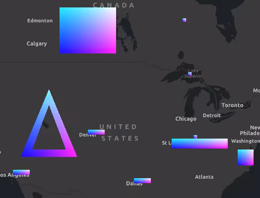 |
vec4(mix(vec3(0.2, 0.3, 0.5), vec3(0.4, 0.5, 0.6), length(v_texcoord) / 1.4142), 1.0) | 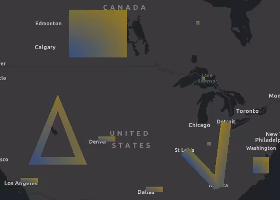 |
vec4(vec3(1.0, 0.0, 0.0) * (1.0 - length(v_texcoord - 0.5)), 1.0) | 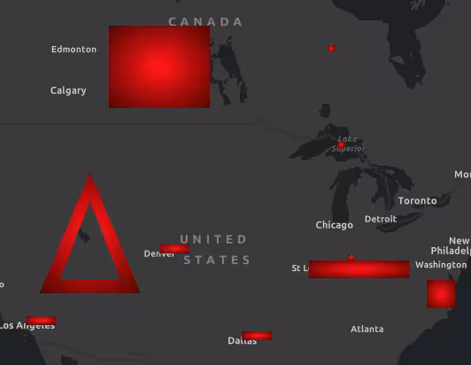 |