Introduction
The demand for managing a diverse range of 3D data is rapidly expanding in web GIS. Given their widespread adoption across various industries, support for 3D models is essential. By utilizing 3D object layers within the

3D object layers
The 3D object layer in
Refer to the accompanying blog post for detailed information on publishing, sharing and working with 3D object layers.
What does this guide cover?
This guide will start by replicating the out-of-the-box editing experience similar to Scene Viewer in your custom app. This workflow utilizing the Editor component will meet the needs of many users. However, some scenarios may require a more tailored approach. To address these scenarios, you will first learn some crucial 3D object layer implementation details. Then, you will delve deeper into implementing custom 3D object layer editing workflows. You will learn how to integrate smaller specialized functions provided by the API into larger functional units. With this knowledge, you will be ready to implement an advanced 3D object editing workflow, similar to the one demonstrated in the SceneLayer Upload 3D Models and ApplyEdits sample.
3D object layer in the SDK
In June 2023,
Out-of-the-box editing functionality
Creating or loading a
Loading an existing web scene
When loading an existing
<!-- Replace with your correctly configured scene's item-id --><arcgis-scene item-id="067ada556ed84bb3aa5c65b4f2a7c15d"></arcgis-scene>// get the Scene component from HTMLconst sceneElement = document.querySelector("arcgis-scene");
await sceneElement.viewOnReady();// The view is now ready to be used.Creating a new web scene
When creating a new
-
The global scene displays 3D features on the globe. Using it assumes that your base maps, elevation, and other layers are available and published in the WGS 1984 or Web Mercator spatial reference and that the 3D object layer is published in the WGS 1984 spatial reference. Set the component’s
viewingModeproperty toglobal. -
The local scene displays 3D features on an approximated flat surface. Using it assumes our layers, base maps, elevation layers, and the 3D object layer are available and published in the desired projected coordinate system. Set the component’s
viewingModeproperty tolocal.
In our example, we are using LV95, a PCS for Switzerland. The following code snippet instantiates an LV95 scene from scratch.
const scene = new WebScene({  basemap: new Basemap({    // LV95 Swiss Topographic (with Contours and Hillshade).    portalItem: { id: "03af6dc44c1e4c948eb87bbaef248f7a" },  }),  ground: {    layers: [      new ElevationLayer({        // LV95 Swiss Terrain 3D.        portalItem: { id: "0eab5ffc50da4cd2afe767c2f2851e30" },      }),    ],  },  layers: [    new SceneLayer({      // Replace with 3D Object (Scene) Layer portal item ID.      portalItem: { id: "replaceMe" },    }),  ],});
// Assign the WebScene instance to the componentsceneElement.map = scene;Using the Editor component
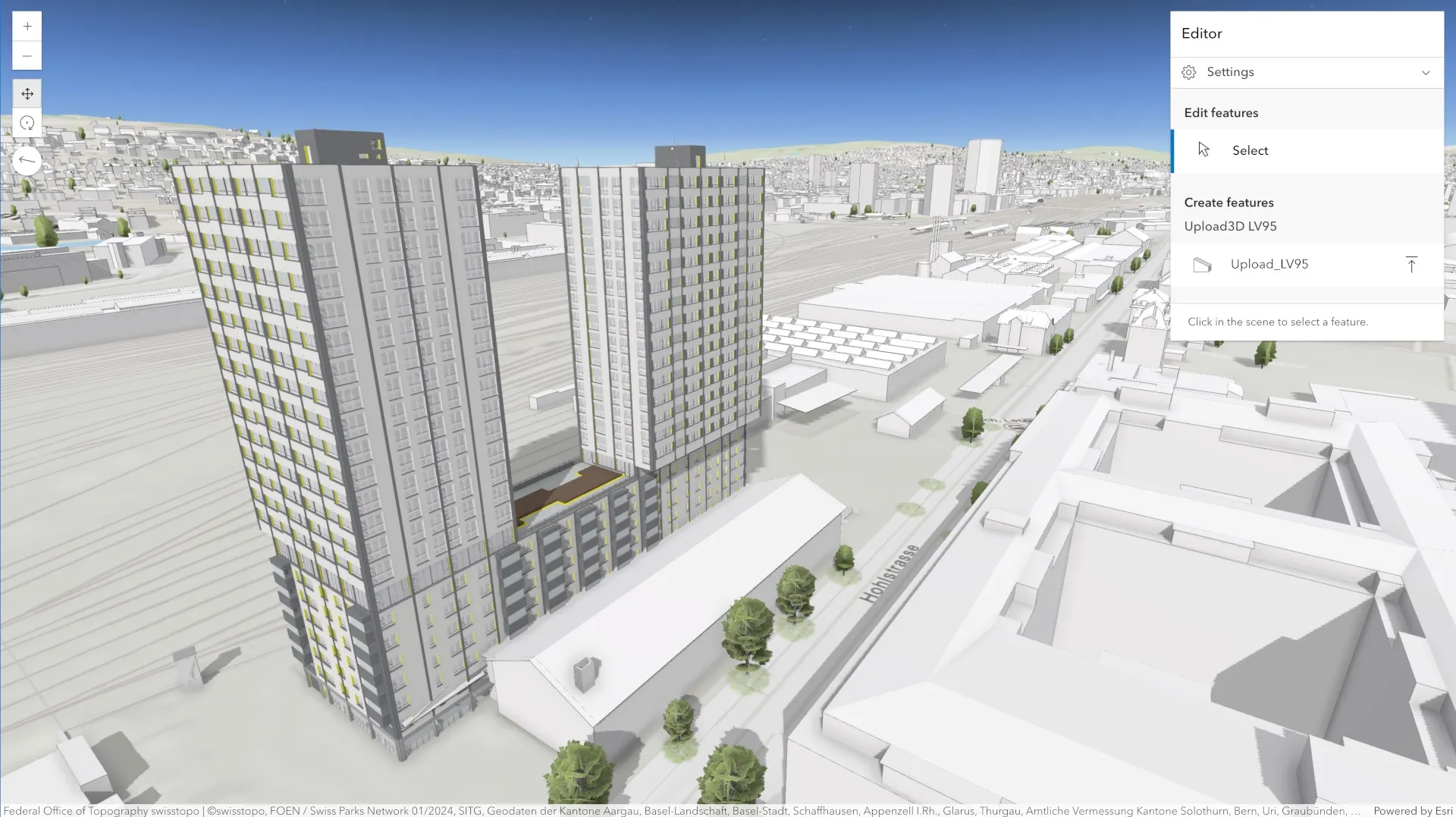
Using the Editor component, you can easily create editing workflows like the one from Scene Viewer. Simply add it to the Scene component.
<arcgis-scene item-id="067ada556ed84bb3aa5c65b4f2a7c15d"> <arcgis-editor slot="top-right"></arcgis-editor></arcgis-scene>You can now edit 3D models like you can in Scene Viewer.
3D object layer implementation in a nutshell
Before diving into the creation of custom 3D object layer editing workflows, it is essential to understand the main principles behind its implementation.
Publishing a 3D object layer creates two
Optimized display and loading
The scene layer represents the data that is optimized for display and loading. This optimization is achieved by organizing multiple 3D features and their attributes into a hierarchical tree structure of nodes, which supports various levels of detail (LoD), texture compression, etc. This structure is efficient because the system only loads and displays features at the appropriate LoD based on the viewing distance, minimizing data transfer and processing.
Database optimized for editing
The primary role of the associated feature layer is to serve as a database for the 3D object layer. When users upload their 3D models (and custom attributes), these are stored within it. The models are then converted to .glb files for display in web browsers and stored alongside the original files in the database. After uploading, the models’
Caching: layer synchronization
The caching process integrates the latest state of the
Updating features: back to the feature layer
When updating of a manipulated feature occurs, its cached copy is invalidated, as it no longer reflects the same position,
Enhanced querying capabilities
When you query the SceneLayer for user-uploaded features, you automatically receive results from the associated feature layer, enabling direct access to the mesh
Essential aspects of the editing workflow
The Editor component streamlines the editing of 3D models, hiding the complexity from the user. However, for custom workflows, you will need to orchestrate the following three essential tasks the Editor performs in the background:
- Format conversion: Your model is converted into mesh geometry and loaded.
- Georeferencing: The model’s origin is georeferenced, and its vertices are projected based on the viewing mode (local/global).
- Storage and updates: The model is stored in the layer and updated upon request.
Format conversion
Before displaying a model in the browser, it must be converted to mesh geometry unless you are loading a glTF (.glb or .glTF) file. There are two methods to create a mesh geometry from a model file:
- Using
createFromGLTF: This method of the Mesh class loads the mesh directly from the glTF data. - Using
convertMesh: This method of the SceneLayer class converts the file to mesh geometry before loading it.
Both methods will be covered in detail with code examples in the continuation of this chapter.
Georeferencing
Every 3D model has an origin, typically located at the coordinate [0, 0, 0] in the modeling software used to create it. All vertices of the model are measured relative to this origin point. Loading and placing your 3D model involves geolocating the model’s origin within a geographic (GCS) or projected coordinate system (PCS) and projecting the model’s vertices accordingly. To geolocate the model’s origin, a Point instance is used, for which you will have to specify two parameters:
Spatial reference: ThespatialReferenceproperty defines the coordinate system used for positioning the model’s origin (geographic or projected). Ensure this property matches your project’s spatial reference. If not specified, it defaults to WGS 1984.Geographic location: Using coordinates, specify where to place the model’s origin. Depending on the spatial reference chosen, you will need to provide either latitude, longitude, and elevation (GCS) coordinates or x, y, and z coordinates (PCS).
Once the model’s origin has been geolocated, the vertices must be projected. The vertexSpace property of the Mesh class dictates how the
- For local scene, always set the
vertexSpaceproperty togeoreferenced. - For global scenes (WGS 1984 or Web Mercator), set it to
local.
To learn more about vertex spaces, consult the
Storage and updates
When working with editable features, you are likely familiar with applyEdits method on the FeatureLayer class. Meshes are just another applyEdits method in the same way as with points, lines, and polygons. The only difference is that for 3D objects, this method is found in the SceneLayer class.
Adding 3D features to the layer
Let’s start by loading and converting some models and displaying them in the scene.
Loading glTF files with the Mesh class
The Mesh class offers an asynchronous createFromGLTF function to load a glTF model (.glTF or .glb) from a URL and into a mesh. The code snippet below demonstrates how to load a model, position it at a designated location in Zurich, Switzerland, using projected coordinates in LV95, and obtain it as a Mesh instance.
// Choose where to place the model (abs. coordinates).const placeTo = new Point({  // Always specify SR! Otherwise WGS84 is assumed.  // We are using the LV95 SR.  spatialReference: { wkid: 2056 },  x: 2687807.511,  y: 1250185.242,  z: 435,});
// Replace with the URL of your 3D model.const model3DURL = "replaceMe.gltf";
const mesh = await Mesh.createFromGLTF(placeTo, model3DURL, {  // Using "georeferenced" as we are working in a PCS.  // vertexSpace: "georeferenced",});
// Wait for the mesh to load.await mesh.load();Loading other supported 3D formats
Only glTF models can be loaded directly as a Mesh. Other formats must be converted server-side through the 3D object layer. For that, you can utilize the convertMesh function available on a SceneLayer instance. This function requires a File array as the first argument and does not directly support URL inputs by default. However, it enables the utilization of a file picker, drag and drop, and other methods available through Web APIs to retrieve the files.
The second argument of convertMesh is an options object that defines where the model will be placed. It works by modifying the origin of the Mesh it returns. If the model contains georeferencing information (for example, IFCv4 files can include offsets, rotations, and metadata to position the model in real-world space) the returned mesh will use that information to compute the origin, effectively placing the model in the correct geographic location. Otherwise, omitting the second argument will set the mesh’s origin to [0, 0, 0].
const mesh = await sceneLayer.convertMesh([file]);Setting the origin property in the second argument overrides any existing georeferencing information in the model.
const mesh = await sceneLayer.convertMesh([file], { origin: placeTo });Alternatively, defaultOrigin acts as a fallback when no georeferencing is present in the model. Models with embedded georeferencing coordinates will still use their own origin, while others will use the provided defaultOrigin.
const mesh = await layer.convertMesh([file], { defaultOrigin: placeTo });When using convertMesh, the vertex space of the converted mesh will be automatically determined based on the spatial reference of the scene layer.
Displaying loaded meshes
To display the resulting mesh geometry, we first create a Graphic and set the mesh as its geometry
// A GraphicsLayer displays all Graphics within it.const graphicsLayer = new GraphicsLayer();sceneElement.map.add(graphicsLayer);
// This symbol will not alter the mesh's appearance.const emptySymbol = new MeshSymbol3D({  symbolLayers: [new FillSymbol3DLayer()],});
const graphic = new Graphic({  geometry: mesh,  symbol: emptySymbol,});
graphicsLayer.add(graphic);
Manipulating the manually placed feature with SketchViewModel
To interact with
// SketchViewModel operates on GraphicsLayer allowing// interactive manipulation of Graphics within it.const sketchVM = new SketchViewModel({ layer: graphicsLayer, view: sceneElement.view, // Enables tooltips (like in Scene Viewer). tooltipOptions: { enabled: true }, // Enables snapping ... snappingOptions: { enabled: true, // ... on geometry of the 3D object layer. featureSources: [{ layer: sceneLayer }], },});Adding the update method selects it and enables interactive manipulation, as shown in the following code snippet and the image below it.
const graphic = new Graphic({  geometry: mesh,  symbol: emptySymbol,});
graphicsLayer.add(graphic);// Select the graphic with the 3D manipulator.sketchVM.update(graphic);
Placing a mesh with SketchViewModel
Previously, we positioned existing meshes using absolute coordinates defined in a Point instance. The place method of the SketchViewModel allows you to interactively position the mesh at the mouse cursor’s location on the map, like with the Editor component. The place method will disregard the coordinates set as the Point attributes. However, it will still utilize the spatialReference property to determine the correct coordinate system, so it is essential to provide this information. Additionally, the place method automatically creates a Graphic from the specified mesh and adds it to the graphics layer, eliminating the need to do it manually.
// Automatically creates a Graphic// and adds it to the graphics layer.sketchVM.place(mesh);Since we enabled tooltips when we initialized the SketchViewModel, pressing the “Tab” key while placing the mesh will now allow you to input coordinates and specify rotation and scale precisely, as illustrated on the image below.
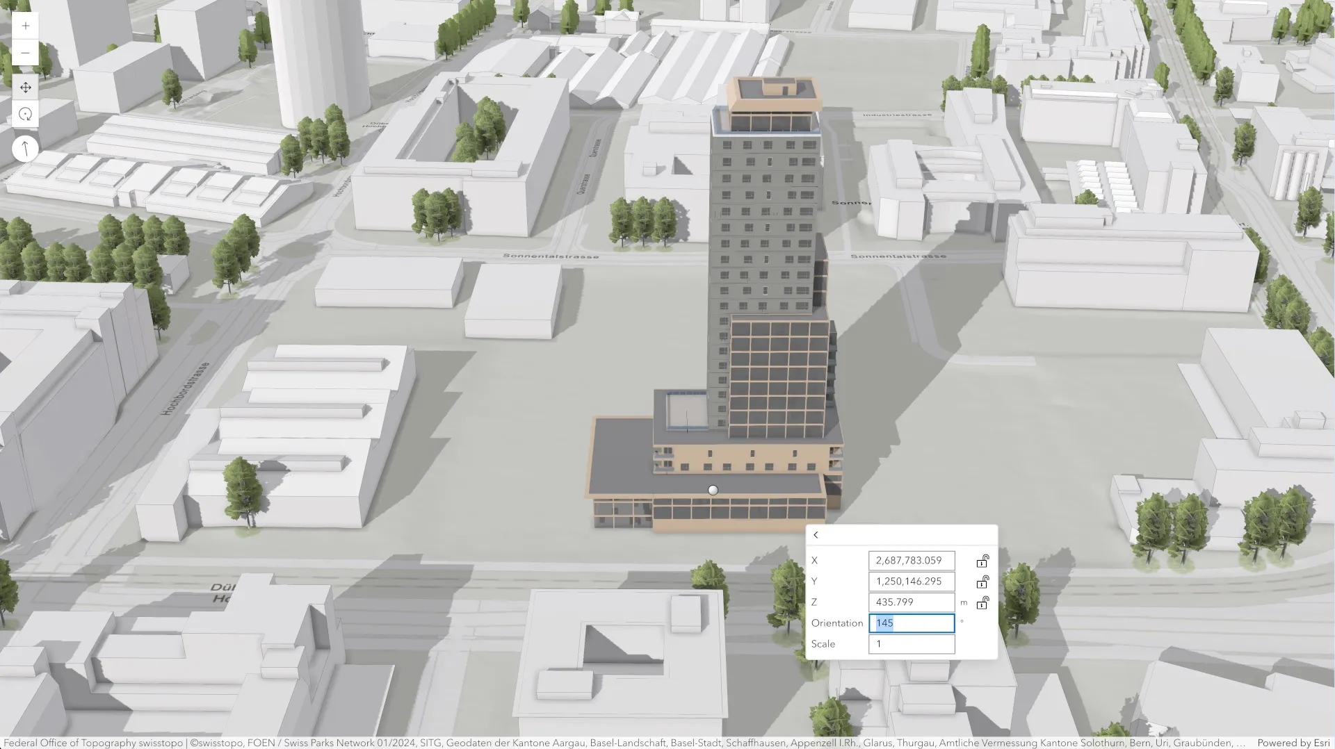
To access the mesh after it has been placed, listen to the create event of the SketchViewModel and proceed when the event’s state equals “complete”. At this point, you can retrieve the final coordinates of the mesh’s origin, modify its appearance, or perform other actions as needed.
sketchVM.on("create", function (event) { if (event.state === "complete") { // Retrieve the final (placed) position of the mesh const mesh = event.graphic.geometry; const placedLocation = mesh.origin; }});Other important event states include start, triggered when the object is selected, and active, which occurs as soon as an action is performed using the 3D manipulator. These events are helpful as they indicate key moments when you might want to hide the model’s geometry from either the GraphicsLayer or the 3D object layer. For an example of using these events effectively, refer to the SceneLayer Upload 3D Models and ApplyEdits sample.
Adding a feature to the database
So far, we have learned how to upload and georeference a 3D model to the desired location in your scene. However, your model is not yet saved in the layer. To persist it, we use the applyEdits method of the SceneLayer class.
The primary parameter for applyEdits is an edits object, which specifies whether we want to add, update, or delete features. This object expects us to pass an array of applyEdits function is asynchronous, and adding features usually takes some time to complete, depending on the size and complexity of your 3D models.
// Take the first graphic from the GraphicsLayerconst [graphic] = graphicsLayer.graphics;
// Use addFeatures property as we are adding a mesh.const edits = { addFeatures: [graphic] };
try {  const result = await sceneLayer.applyEdits(edits);  console.log("Edits applied successfully:", result);} catch (err) {  // Deal with the error.}
Once the process is finished, your 3D model will be successfully saved in the associated feature layer with unique globalId and objectId attributes. The globalId attribute will also be added to the provided Graphic, which can be used to identify it. After applyEdits is completed, there will be two visible instances of the same mesh geometry (in GraphicsLayer and in the 3D object layer), and you should decide which one to hide.
Querying, updating, and deleting features
At this stage, we know how to upload, georeference, and persist the model in the layer. The stored models are in the database and are displayed either directly from it or from the scene layer cache (if caching was done after adding them). In any case, to manipulate and update the persisted models, we first need to retrieve them, which involves querying the 3D object layer.
Querying a SceneLayer instance retrieves results from the attributes of its associated feature layer. If there is no associated feature layer, the query will result in an error. To determine if the layer has an associated feature layer, we can use supportsReturnMesh property to check if it is capable of returning mesh geometry. If it is capable, this indicates that the associated 3D object feature layer exists and can be queried.
// Load the scene layer to check its capabilities.await sceneLayer.load();// Check if the layer is capable of returning mesh geometry.if (sceneLayer.capabilities.query.supportsReturnMesh) { console.log("The associated FL exists and can be queried.");}We can query the layer in various ways and retrieve the feature’s
For more information on querying in the
Query class, and the related
guide page.
Querying by features’ unique ID
When you add a feature to the layer, it is assigned an objectId attribute, a unique non-zero integer. Using the query’s objectId property, you can retrieve one or more features based on the provided IDs. For example, to zoom in on a set of features, you can query the
const query = sceneLayer.createQuery();// Replace with feature's objectId (non-zero integer).query.objectIds = [2];
try {  const response = await sceneLayer.queryExtent(query);  // Change the view to the selected object's extent.  await sceneElement.goTo({ target: response.extent, tilt: 60 });} catch (err) {  // Deal with the error.}
Spatial querying
You can also query objects according to their spatial relationships to other objects. For example, you can draw a
var polygon = new Polygon({ rings: [ [ // First ring. [x1, y1, z1], // Point 1. [x2, y2, z2], // Point 2 // Other points ... ], [ // Second ring. // Other points ... ], ], spatialReference: { wkid: 2056 },});When creating a query, use the geometry property to specify the spatial object that restricts the query results. Use the spatialRelationship property to set how this geometry should influence the results. Here, we are setting the polygon as the geometry and choosing the intersection as the spatial relationship. Instead of querying the object’s extent, we use the queryObjectIds method to retrieve the IDs of affected 3D features.
var query = sceneLayer.createQuery();query.geometry = polygon;query.spatialRelationship = "intersects";
try {  const response = await sceneLayer.queryObjectIds(query);  // Use IDs for something ...} catch (err) {  // Deal with the error.}
Retrieving the feature’s mesh geometry
Finally, by setting the returnGeometry property to true and using the queryFeatures method, we can retrieve the 3D object’s geometry as a Graphic containing a mesh.
const query = sceneLayer.createQuery();query.returnGeometry = true;// Replace with feature's ObjectID (non-zero integer).query.objectIds = [2];
try {  const response = await sceneLayer.queryFeatures(query);  const mesh = response.features[0].geometry;  // Use the mesh ...} catch (err) {  // Deal with the error.}
If you are only interested in retrieving the feature’s xy footprint as geometry, set the multipatchOption property to xyFootprint.
// Returns the xy footprint of each feature in the result.query.multipatchOption = "xyFootprint";Selecting 3D features with a mouse-click event
When making a custom app, it is very useful to be able to click on the stored 3D model and select it. When using the Scene component, you can listen to its arcgisViewClick event and call its hitTest method to identify the 3D model closest to the
sceneElement.addEventListener("arcgisViewClick", async (event) => {  const hitTestResults = await sceneElement.hitTest(event.detail);  if (!hitTestResults) {    return;  }
  // Filter Graphic objects.  const graphicHits = hitTestResults.results.filter((result) => result.type === "graphic");  if (graphicHits.length === 0) {    return;  }
  // Get the Graphic closest to the camera (the first one).  const userGraphic = graphicHits[0].graphic;  // Get the attribute name that refers to the object ID.  const { objectIdField } = sceneLayer;  // Get the feature's objectId  const objectId = userGraphic.attributes[objectIdField];  console.log(`Object with objectId: ${objectId}`);});
Once you have the correct objectId, you can proceed to query the SceneLayer instance and retrieve the feature as a Graphic. The Graphic can then be added to the GraphicsLayer and SketchViewModel for seamless editing, as shown earlier.
To hide the instance from the layer, use the following snippet.
sketchVM.on("update", async (event) => { // When the model is selected. if (event.state === "start") { const [graphic] = event.graphics; // Get the attribute name that refers to the object ID. const { objectIdField } = sceneLayer; // Hide the object with the same objectId. sceneLayer.excludeObjectIds.add(graphic.attributes[objectIdField]); }});Updating features in the 3D object layer
After retrieving a model from the layer, you may want to move, rotate, or scale it and then save the updated state. Updates to existing features are made using the applyEdits method with the updateFeatures property, which accepts an array of graphics. To identify which models to update in the 3D object layer when editing the corresponding graphics, the globalId attribute, which must be present in both instances (the attribute was initially added when we used applyEdits with addFeatures). Since interactively manipulating the feature only modifies its mesh transform attributes, updating the manipulated feature is significantly faster than initially adding it. Below is an example of how to update the feature after manipulating it.
// Using updateFeatures property as we are updating// a mesh that already exists in the feature layer.const edits = { updateFeatures: [graphic] };
try {  const response = await sceneLayer.applyEdits(edits);  console.log("Update applied succesfully:", response);} catch (err) {  // Deal with the error.}
Deleting features from the 3D object layer
Deleting features from the 3D object layer follows the same pattern as with addFeatures and updateFeatures.
// Using deleteFeatures property as we are deleting// data that already exists in the feature layer.const edits = { deleteFeatures: [graphic] };
try {  const response = await sceneLayer.applyEdits(edits);  console.log("Features deleted succesfully:", response);} catch (err) {  // Deal with the error.}
What’s next?
Congratulations on completing this guide! We’ve covered a wide range of topics, and learned how to implement various aspects of custom 3D object workflows using the