Learn how to set a basemap, elevation source, add data layers, and display a specific area using the Modes Panel UI.
In this tutorial, you will create a local scene in Unreal Engine that contains a basemap layer service

Prerequisites
Before starting this tutorial, review the following guidelines:
- You need an ArcGIS Location Platform account or ArcGIS Online account and an API key
An API key is a long-lived access token created using API key credentials. They are valid for up to one year and are typically embedded directly into client applications. to access ArcGIS servicesA service, also known as an ArcGIS service, is software that supports an ArcGIS REST API and provides geospatial functionality or data. A service can be hosted by Esri or in ArcGIS Enterprise. . If you don't have an account, sign up for free. - Ensure your development environment meets the system requirements.
- Follow the install and setup steps and install the plugin. Make sure to import the sample assets.
- Review the scene setting options page.
If you are not familiar with the Unreal Engine's interface, see Unreal Editor Interface for information about the most common editor panels, and how to use them.
Steps
Create a new level and open the Modes Panel UI
-
Click File on the Menu Bar and select New Level.
-
If using a blank template from the games category for your project, select Empty Level in the popup window.
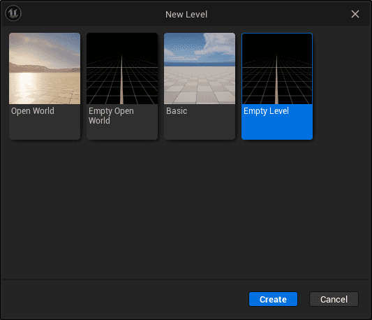
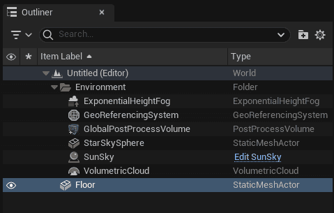
If using a simulation blank template from the simulation category for your project, select Simulation Blank in the popup window,
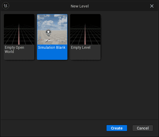
and remove the included Floor static mesh actor from the Outliner window.
-
Click File on the Menu Bar and select Save Level As. Name your level and click Save.
Create a map
-
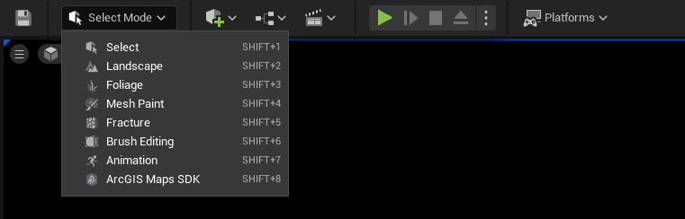
Click the Select Mode drop-down menu in the Unreal UI toolbar and select ArcGIS Maps SDK.
-
The Modes Panel UI opens at the left of the Unreal Editor interface.

-
In the Modes Panel UI, click the Map tab.
-
Select
Localfor the Map Type. -
In the Origin Position section, set the center of your GIS scene with coordinates and a Well-Known ID (WKID) spatial reference. For the tutorial, set the parameters to these values:
- Longitude: -74
- Latitude: 41
- Altitude: 0
- Spatial Reference WKID: 4326
For information regarding the spatial reference, see the spatial references page.
-
Check the Is Extent Enabled checkbox to display the Map Extent section
-
In Map Extent, set the extent of the map to these values:
- Longitude: -74.0
- Latitude: 40.72
- Spatial Reference WKID: 4326
- Extent Shape: Circle
- Radius: 5000
This is the result of the updated Map tab:

-
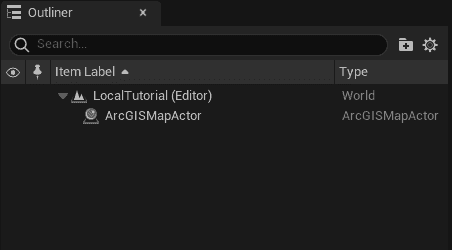
Click the Create button. In the Outliner panel, the ArcGISMapActor is created.
Create and set up a camera
ArcGIS Maps SDK for Unreal Engine will show higher resolution LODs for areas closer to the camera and lower resolution LODs for areas that are farther away from the camera.
-
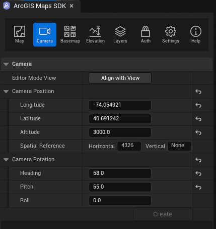
Click the Camera tab.
-
The Camera Position defines the initial point of view of the camera. Set the parameters to these values:
- Longitude: -74.054921
- Latitude: 40.691242
- Altitude: 3000
- Spatial Reference WKID: 4326
-
The Camera Rotation defines the angle of the camera. Set the parameters to these values:
- Heading: 55
- Pitch: 58
- Roll: 0
This is the result of the updated Camera tab:
-
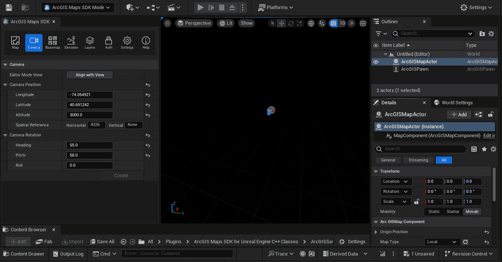
Click the Create button. In the Outliner panel, the Default Pawn Actor is created.

The level will still be empty at this point. In the coming tutorial steps, map data will be added to the level.
Set basemap and API key
In this tutorial, you will select a basemap that requires an API key.
-
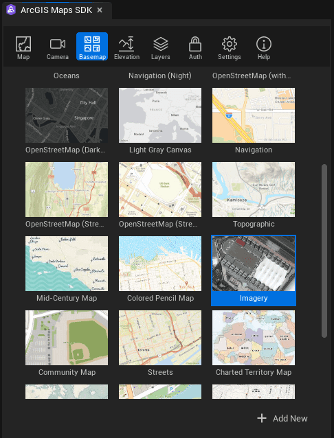
Click the Basemap tab and display the panel content.
-
Select the Imagery basemap from the preset basemap list.
This is the result of setting up the basemap to Imagery from the preset basemap.

-
Go to your portal to get your API key.
-
Click the Auth tab to display the panel content.
-
Set the API key in the API Key section.
Make sure your API key is in the field where you see
Paste your APin this screenshot. You can find the information about how to get API keys by clicking on Get an API Key in the UI.I key here 
-
After switching back to the Basemap tab, the previously grayed-out basemap icons should now be enabled, indicating that the API key is successfully registered.
Another way to set up a global API key for multiple levels in your Unreal project is through Project Settings. For more information about the API key, refer to the API keys section.
Set elevation
In this tutorial, you will use the default elevation to define the terrain.
-
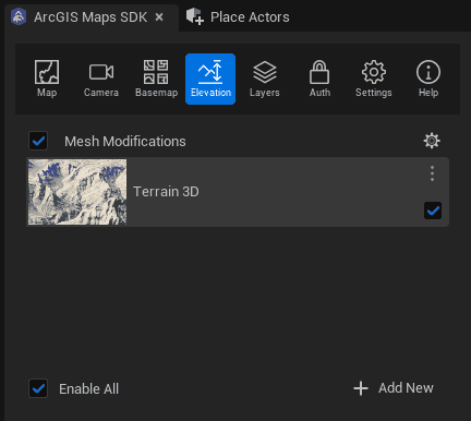
Click the Elevation tab and display the panel content.
-
Make sure Terrain 3D is selected and the Enable All checkbox is checked.
This is the result of the elevation panel.
Add data layers
You will add operational data from ArcGIS Online
- ArcGIS Online item: UrbanObservatory_NYC_TransitFrequency
- Layer name:
01 - New York Transit Frequency - Type:
ArcGIS Image Layer - Item page URL:
Use dark colors for code blocks Copy https://www.arcgis.com/home/item.html?id=b3a3743cda50473ba5df14eaf14e5d18- Opacity:
0.9
- Opacity:
- ArcGIS Online item: New_York_Industrial
- Layer name:
02 - New York Industrial Areas - Type:
ArcGIS Image Layer - Item page URL:
Use dark colors for code blocks Copy https://www.arcgis.com/home/item.html?id=1c28f1944276445a99f5b554c3c07771- Opacity:
0.6
- Opacity:
- ArcGIS Online item: NewYorkCity_PopDensity
- Layer name:
03 - New York Population Density - Type:
ArcGIS Image Layer - Item page URL:
Use dark colors for code blocks Copy https://www.arcgis.com/home/item.html?id=7de726fabcc149f185b0bf8acde82878- Opacity:
1.0
- Opacity:
- ArcGIS Online item: New York, USA Buildings
- Layer name:
04 - New York Buildings - Type:
ArcGIS 3 D Object Scene Layer - Item page URL:
Use dark colors for code blocks Copy https://www.arcgis.com/home/item.html?id=a457834a6cb449cd958502d6e98ba305- Opacity:
1.0
- Opacity:
Follow these steps to add each layer.
-
Click the Layers tab.
-
In the Add Data section, select the appropriate layer type from the drop-down list in Type.
-
Enter the layer's online service URL in the Source field to add an image tile layer.
-
Type the layer name in the Name field.
-
Click the Add button to add a layer to your map. Once the layer is added, it will appear in the Layers section.
-
Set the Opacity by dragging the slider to a specific value.
-
Use the layer checkbox (above the layer name field) to toggle the layer visibility.
This is the result of the Layers panel.

Set up sky and lighting
-
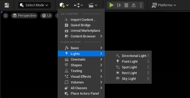
From the Create menu on the Main Toolbar, select Lights > Directional Light and drag it into the level to create a Directional Light. For more information about Directional Lights, see Lights.
-
Select the Directional Light in the Outliner, and open the Transform section in the Details panel.
-
Reset the Location and Set the Rotation to:
- X: 0
- Y: -28
- Z: -28
-
Set the Mobility to Movable.

-
In the Light section, change the Intensity Value to
3.1416. -
In the Cascaded Shadow Maps section, change the Dynamic Shadow Distance MovableLight to
2000000. -
In the Atmosphere and Cloud section, enable Atmosphere Sun Light.
-
In the Actor > Spawn Collision Handling Method section, select Always Spawn, Ignore Collisions.

-
From the quick add menu on the toolbar, select Lights > Sky Light and drag it into the level to create a Sky Light. For more information about Sky Light, see Lights.
-
In the Transform section, reset the Location and set the Mobility to Movable.
-
In the Light section, enable Real Time Capture.

-
From the quick add menu on the toolbar, select Visual Effects > Sky Atmosphere and drag it into the level to create a Sky. For more information about Sky Atmosphere, see Fog Effects.
-
In the Planet section, change the Ground Radius to
6378.137207.
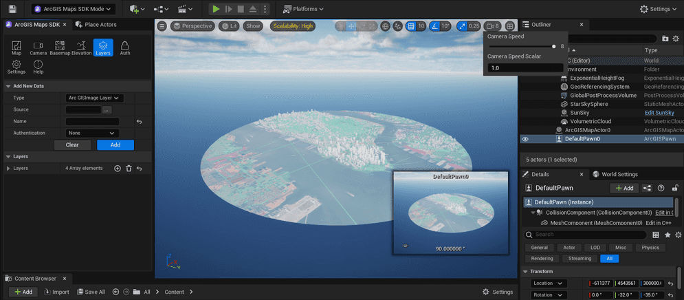
At this point, you should see the cropped map data with the extent configuration.
- In the Outliner panel, double-click the Default Pawn to move the Editor camera to the configured camera position.
- Use the WASD keys while holding down the right mouse button to move around or hold down the left mouse button to look around in Editor mode.
- To increase the camera navigation speed in the Viewport in Editor mode, click the Camera Speed icon in the top right corner of the Viewport and increase the value by dragging the slider.

Replace the Default Pawn with the ArcGIS Pawn
In Editor mode, you can freely navigate the scene using the standard viewport controls in Unreal Engine. To navigate the scene in Play mode, you can write your own controller Component for the Pawn or modify the movement component in the Default Pawn. In addition, you can replace the Default Pawn with the sample ArcGIS Pawn that is used in the sample levels. For information about the sample ArcGIS Pawn, see the ArcGIS Pawn section.
-
Open the location below in the Content Drawer.
Plugins > ArcGIS Maps SDK for Unreal Engine C++ Classes > ArcGISSamples > Public
-
Click the ArcGIS Pawn to select it. When it is selected the background color changes to blue.
-
Right click the Default Pawn in the Outliner panel.
-
Click Replace Selected Actor with, then select ArcGIS Pawn.
You have successfully configured the local scene with the Modes Panel UI.
Click the Play icon on the Toolbar, and use the WASD keys to move around, hold the right mouse button mouse to look around or hold the left mouse button to pan.