This sample demonstrates how to extrude building footprints (polygon features) in 3D based on a real-world height stored in an attribute field. In some cases users only want to know where features are located, such as project areas, roads, buildings, etc. The data may be stored in a single layer where all features must be visualized with the same symbol or as unique types.
In this case, we’ll use a UniqueValueRenderer to shade each feature based on it’s building type. We’ll also use visual variables to extrude each feature based on a numeric attribute.
1. Create a symbol for each type
While all symbol types are supported in 3D, it is recommended to only use 3D symbols when working with a Scene component.
Because features in the building footprints layer are polygons, we need to create a PolygonSymbol3D for each type of building that will have a different color. PolygonSymbol3D along with all other 3D symbols is a container that holds one or more symbol layers. It is the Symbol3DLayer classes that define the color and size of 3D symbols.
In this case we need to add an ExtrudeSymbol3DLayer to the PolygonSymbol3D so that we can extrude the polygons from the surface. To better distinguish the 3D shape of the extrusion we set the edges property on ExtrudeSymbol3DLayer, to render the contour edges.
To read more in depth about 3D symbols and their relationship to symbol layers, see the documentation for Symbol3D, Symbol3DLayer, and their subclasses. In the example below we generate the symbols with a function.
function getSymbol(color) { return { type: "polygon-3d", // autocasts as new PolygonSymbol3D() symbolLayers: [ { type: "extrude", // autocasts as new ExtrudeSymbol3DLayer() material: { color: color, }, edges: { type: "solid", color: "#999", size: 0.5, }, }, ], };}2. Create an instance of UniqueValueRenderer
We must use a UniqueValueRenderer when defining how features should be visualized based on field values. Up to three fields may be used to create various combinations of types. In this case we’re shading features with different colors based on one field: TYPE.
const renderer = { type: "unique-value", // autocasts as new UniqueValueRenderer() // the default symbol indicates all other building types defaultSymbol: getSymbol("#FFFFFF"), defaultLabel: "Other", field: "TYPE", // building type};3. Match unique values with each symbol
You can match symbols with unique field values in one of two ways: Using uniqueValueInfos in the constructor…
const renderer = {  type: "unique-value", // autocasts as new UniqueValueRenderer()  // the default symbol indicates all other building types  defaultSymbol: getSymbol("#FFFFFF"),  defaultLabel: "Other",  field: "TYPE",
  // match symbols to unique values here  uniqueValueInfos: [    {      value: "Residential",      symbol: getSymbol("#A7C636"),      label: "Residential",    },    {      value: "Commercial",      symbol: getSymbol("#FC921F"),      label: "Commercial",    },    {      value: "Hotel/Motel",      symbol: getSymbol("#ED5151"),      label: "Hotel/Motel",    },    {      value: "Apartment Rentals",      symbol: getSymbol("#149ECE"),      label: "Apartment Rentals",    },  ],};
Or with the addUniqueValueInfo() method.
hwyRenderer.addUniqueValueInfo("Residential", getSymbol("#A7C636"));4. Add a size visual variable to extrude real-world heights
Finally, to extrude the real-world heights of each building, we’ll add a size visual variable to the visualVariables array in the renderer. This requires only three properties: the type, field name, and valueUnit if the extrusion value is in any unit other than meters. In this case, the extrusion value is in meters so we only set the type and the field.
const renderer = {  type: "unique-value", // autocasts as new UniqueValueRenderer()
  // set properties from previous steps here
  // define size visual variable based on height values in a field  visualVariables: [    {      type: "size",      field: "HEIGHT",    },  ],};
5. Summary
Once the renderer is defined, you can set it on the layer and the view will automatically update.
Related samples and resources
Scale feature sizes based on real world sizes (2D)
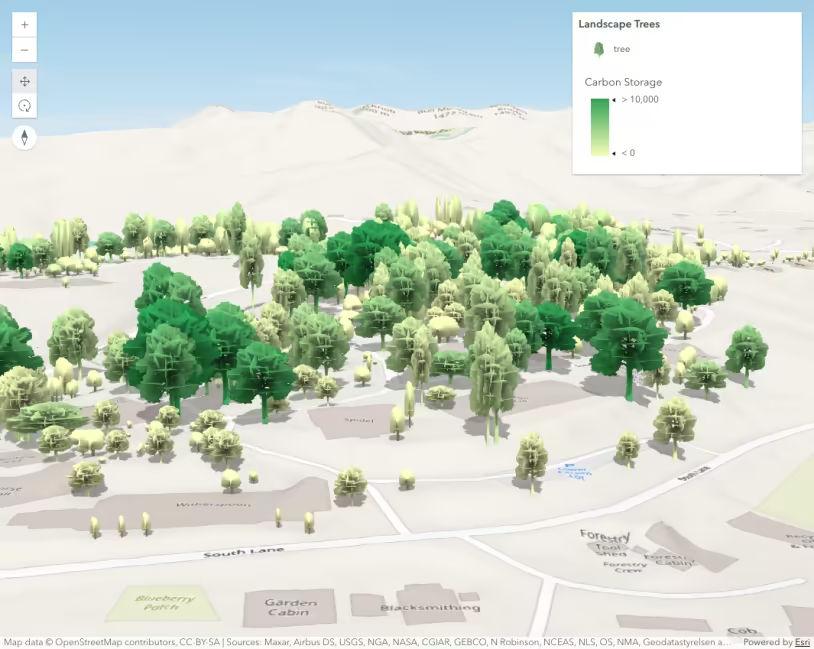
Thematic visualization with realistic 3D symbols
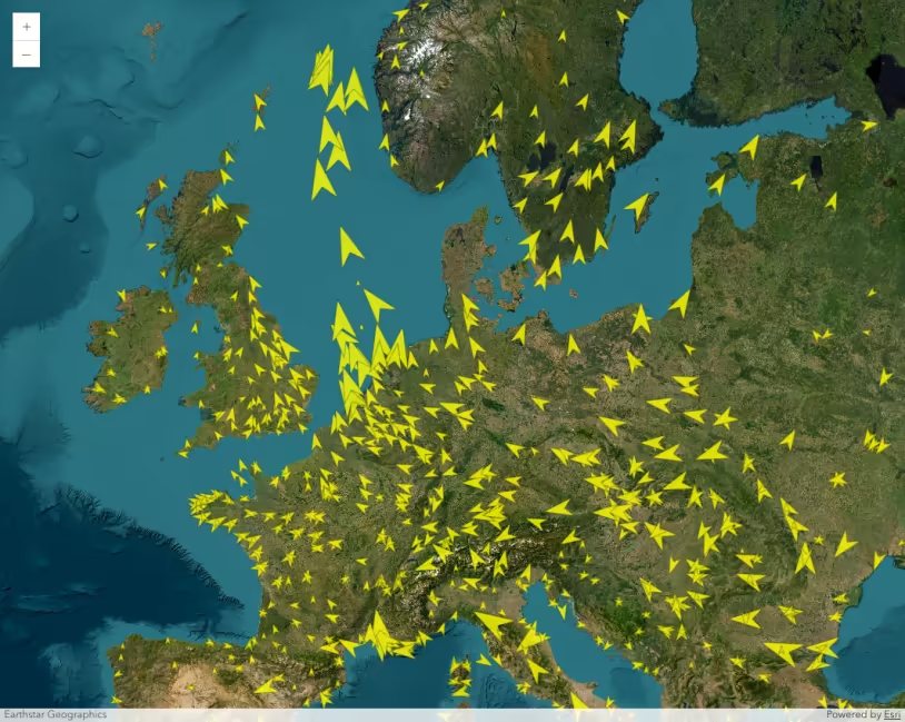
Visualize data with rotation
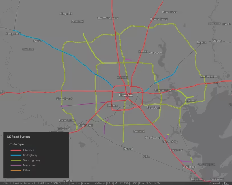
Visualize features by type
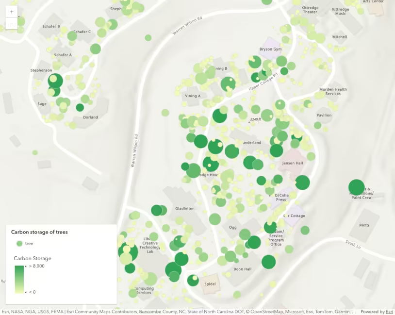
Data-driven continuous color
Data-driven continuous size
