import LinkChartLayer from "@arcgis/core/layers/LinkChartLayer.js";const LinkChartLayer = await $arcgis.import("@arcgis/core/layers/LinkChartLayer.js");- Since
- ArcGIS Maps SDK for JavaScript 4.31
A LinkChartLayer is a composite layer that can be created from a knowledge graph service. The layer contains sublayers for each entity type and relationship type contained in the LinkChartLayer.
Entity and relationship types have geometries that allows them to be rendered in a LinkChartView or as a Graphic with spatial context. They also contain data Graphic.attributes that provide additional information about the real-world feature it represents; Attributes may be viewed in popups and used for rendering the layer. Sublayers may be queried, analyzed, and rendered to visualize data in a spatial context.
Implementation Note
Link chart layers are not dynamic. If no inclusion definition is specified, the inclusion definition will be defined as all records in the graph at the time of layer creation. If a named type is specified with no explicit members, then all records of that named type will be defined as the inclusion definition. Any data added to the graph or named type after this point will not be included in the link chart.
Create Link Chart Layer
To create a LinkChartLayer from knowledgeGraphService, you must set the url property to the REST endpoint of the service. For a layer to be visible in a view, it must be added to the WebLinkChart referenced by the view. See WebLinkChart for information about adding layers to a WebLinkChart.
const [LinkChartLayer, WebLinkChart, LinkChartView] = await $arcgis.import([ "@arcgis/core/layers/LinkChartLayer.js", "@arcgis/core/WebLinkChart.js", "@arcgis/core/LinkChartView.js"]);const myLinkChartLayer = new LinkChartLayer({ title: "link chart layer", url: "https://sampleserver7.arcgisonline.com/arcgis/rest/services/Hosted/SmallBumbleBees/KnowledgeGraphServer"});myLinkChartLayer.load().then(()=>{ const linkchart = new WebLinkChart({ layers: [myLinkChartLayer] });})Constructors
Constructor
Parameters
| Parameter | Type | Description | Required |
|---|---|---|---|
| properties | | |
Properties
| Property | Type | Class |
|---|---|---|
blendMode inherited | ||
declaredClass readonly inherited | ||
effect inherited | ||
fullExtent inherited | ||
id inherited | ||
| | ||
| | ||
layers readonly | | |
listMode inherited | ||
loaded readonly inherited | ||
loadError readonly inherited | ||
loadStatus readonly inherited | "not-loaded" | "loading" | "failed" | "loaded" | |
loadWarnings readonly inherited | any[] | |
maxScale inherited | ||
| | ||
| | ||
minScale inherited | ||
opacity inherited | ||
parent inherited | Map | Basemap | Ground | GroupLayer | CatalogDynamicGroupLayer | CatalogLayer | null | undefined | |
persistenceEnabled inherited | ||
tables readonly | | |
| | ||
type readonly inherited | ||
uid readonly inherited | ||
| | ||
visibilityTimeExtent inherited | TimeExtent | null | undefined | |
visible inherited |
blendMode
- Type
- BlendMode
Blend modes are used to blend layers together to create an interesting effect in a layer, or even to produce what seems like a new layer. Unlike the method of using transparency which can result in a washed-out top layer, blend modes can create a variety of very vibrant and intriguing results by blending a layer with the layer(s) below it.
When blending layers, a top layer is a layer that has a blend mode applied. All layers underneath the top layer are background layers.
The default blending mode is normal where the top layer is simply displayed over the background layer. While this default behavior is perfectly acceptable,
the use of blend modes on layers open up a world of endless possibilities to generate creative maps.
The layers in a GroupLayer are blended together in isolation from the rest of the map.
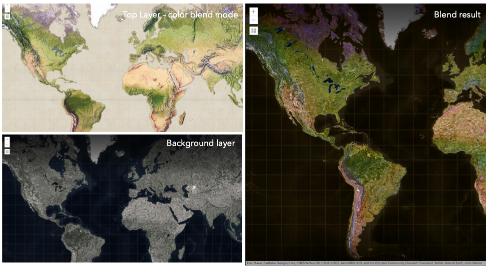
In the following screenshots, the vintage shaded relief
layer is displayed over a firefly world imagery layer. The color blend mode
is applied to the vintage shaded relief and the result looks like a new layer.
Known Limitations
- In 3D SceneViews, the blendMode is supported on BaseTileLayer, ImageryTileLayer, OpenStreetMapLayer, TileLayer, VectorTileLayer, WCSLayer, WebTileLayer, WMTSLayer and GroupLayer.
- When working with GroupLayers in a 3D SceneView, the blendMode is only applied to the sublayers that support it.
- The blendMode is not supported in the Legend.
- See print for known printing limitations.
The following factors will affect the blend result:
- Order of all layers
- Layer opacity
- Opacity of features in layers
- Visibility of layers
- By default, the very bottom layer in a map is drawn on a transparent background. You can change the MapView's background color.
Read More
| Blend mode | Description |
|---|---|
| normal | The top layer is displayed over the background layer. The data of the top layer block the data of background layer where they overlap. |
| average | Takes the mathematical average of top and background layers. Result of average blend mode is often similar to the effect of setting the layer's opacity to 50%. |
Lighten blend modes:
The following blend modes create lighter results than all layers. In lighten blend modes, pure black colors in the top layer become transparent allowing the background layer to show through. White in the top layer will stay unchanged. Any color that is lighter than pure black is going to lighten colors in the top layer to varying degrees all way to pure white.
Lighten blend modes can be useful when lightening dark colors of the top layer or removing black colors from the result.
The plus, lighten and screen modes can be used to brighten layers that have faded or dark colors on a dark background.
| Blend mode | Description |
|---|---|
| lighten | Compares top and background layers and retains the lighter color. Colors in the top layer become transparent if they are darker than the overlapping colors in the background layer allowing the background layer to show through completely. Can be thought of as the opposite of darken blend mode. |
| lighter | Colors in top and background layers are multiplied by their alphas (layer opacity and layer's data opacity. Then the resulting colors are added together. All overlapping midrange colors are lightened in the top layer. The opacity of layer and layer's data will affect the blend result. |
| plus | Colors in top and background layers are added together. All overlapping midrange colors are lightened in the top layer. This mode is also known as add or linear-dodge. |
| screen | Multiplies inverted colors in top and background layers then inverts the colors again. The resulting colors will be lighter than the original color with less contrast. Screen can produce many different levels of brightening depending on the luminosity values of the top layer. Can be thought of as the opposite of the multiply mode. |
| color-dodge | Divides colors in background layer by the inverted top layer. This lightens the background layer depending on the value of the top layer. The brighter the top layer, the more its color affects the background layer. Decreases the contrast between top and background layers resulting in saturated mid-tones and blown highlights. |
Darken blend modes:
The following blend modes create darker results than all layers. In darken blend modes, pure white in the top layer will become transparent allowing the background layer to show through. Black in the top layer will stay unchanged. Any color that is darker than pure white is going to darken a top layer to varying degrees all the way to pure black.
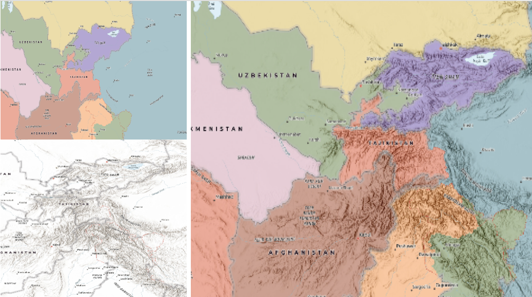
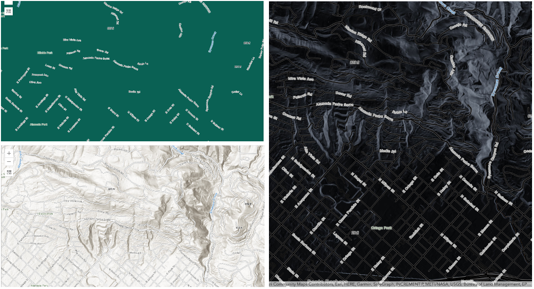
The multiply blend mode is often used to highlight shadows, show contrast, or accentuate an aspect of a map. For example, you can use multiply blend mode on a topographic map
displayed over hillshade when you want to have your elevation show through the topographic layer. See the intro to layer blending sample.
The multiply and darken modes can be used to have dark labels of the basemap to show through top layers. See the darken blending sample.
The color-burn mode works well with colorful top and background layers since it increases saturation in mid-tones. It increases the contrast by tinting pixels in overlapping areas in
top and bottom layers more towards the top layer color. Use this blend mode, when you want an effect with more contrast than multiply or darken.
The following screenshots show how the multiply blend mode used for creating a physical map of the world that shows both boundaries and elevation.
| Blend mode | Description |
|---|---|
| darken | Emphasizes the darkest parts of overlapping layers. Colors in the top layer become transparent if they are lighter than the overlapping colors in the background layer, allowing the background layer to show through completely. |
| multiply | Emphasizes the darkest parts of overlapping layers by multiplying colors of the top layer and the background layer. Midrange colors from top and background layers are mixed together more evenly. |
| color-burn | Intensifies the dark areas in all layers. It increases the contrast between top and background layers, by tinting colors in overlapping area towards the top color. To do this it inverts colors of the background layer, divides the result by colors of the top layer, then inverts the results. |
Contrast blend modes:
The following blend modes create contrast by both lightening the lighter areas and darkening the darker areas in the top layer by using lightening or darkening blend modes to create the blend.
The contrast blend modes will lighten the colors lighter than 50% gray ([128,128,128]), and darken the colors darker than 50% gray. 50% gray will be transparent in the top layer.
Each mode can create a variety of results depending on the colors of top and background layers being blended together.
The overlay blend mode makes its calculations based on the brightness of the colors in the background layer while all of the other contrast blend modes make their calculations based on the brightness of the top layer.
Some of these modes are designed to simulate the effect of shining a light through the top layer, effectively projecting upon the layers beneath it.
Contrast blend modes can be used to increase the contrast and saturation to have more vibrant colors and give a punch to your layers.
For example, you can duplicate a layer and set overlay blend mode on the top layer to increase the contrast and tones of your layer.
You can also add a polygon layer with a white fill symbol over a dark imagery layer and apply soft-light blend mode to increase the brightness in the imagery layer.
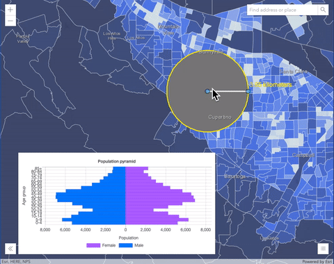
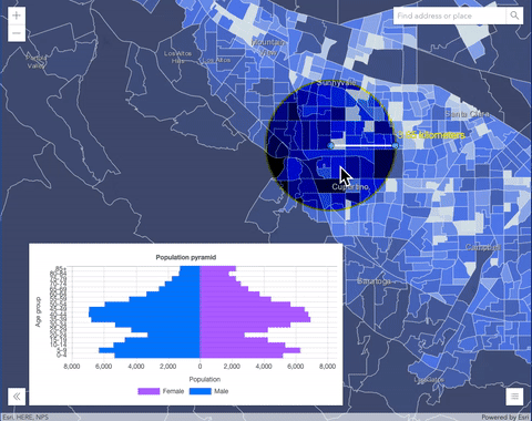
The following screenshots show an effect of the overlay blend mode on a GraphicsLayer. The left image shows when the buffer graphics layer has the normal blend mode.
As you can see, the gray color for the buffer polygon is blocking the intersecting census tracts. The right image shows when the overlay blend mode is applied to the buffer graphics layer.
The overlay blend mode darkens or lightens the gray buffer polygon depending on the colors of the background layer while the census tracts layer is shining through.
See this in action.
| Normal blend mode | Overlay blend mode |
|---|---|
 |  |
| Blend mode | Description |
|---|---|
| overlay | Uses a combination of multiply and screen modes to darken and lighten colors in the top layer with the background layer always shining through. The result is darker color values in the background layer intensify the top layer, while lighter colors in the background layer wash out overlapping areas in the top layer. |
| soft-light | Applies a half strength screen mode to lighter areas and half strength multiply mode to darken areas of the top layer. You can think of the soft-light as a softer version of the overlay mode. |
| hard-light | Multiplies or screens the colors, depending on colors of the top layer. The effect is similar to shining a harsh spotlight on the top layer. |
| vivid-light | Uses a combination of color-burn or color-dodge by increasing or decreasing the contrast, depending on colors in the top layer. |
Component blend modes:
The following blend modes use primary color components, which are hue, saturation and luminosity to blend top and background layers.
You can add a feature layer with a simple renderer over any layer and set hue, saturation, color or luminosity blend mode on this layer. With this technique, you create a brand new looking map.
The following screenshots show where the topo layer is blended with
world hillshade layer with luminosity blend mode.
The result is a drastically different looking map which preserves the brightness of the topo layer while adapting the hue and saturation of the hillshade layer.
| Blend mode | Description |
|---|---|
| hue | Creates an effect with the hue of the top layer and the luminosity and saturation of the background layer. |
| saturation | Creates an effect with the saturation of the top layer and the hue and luminosity of the background layer. 50% gray with no saturation in the background layer will not produce any change. |
| luminosity | Creates effect with the luminosity of the top layer and the hue and saturation of the background layer. Can be thought of as the opposite of color blend mode. |
| color | Creates an effect with the hue and saturation of the top layer and the luminosity of the background layer. Can be thought of as the opposite of luminosity blend mode. |
Composite blend modes:
The following blend modes can be used to mask the contents of top, background or both layers.
Destinationmodes are used to mask the data of the top layer with the data of the background layer.Sourcemodes are used to mask the data of the background layer with the data of the top layer.
The destination-in blend mode can be used to show areas of focus such as earthquakes, animal migration, or point-source pollution by revealing the underlying map,
providing a bird's eye view of the phenomenon. Check out multiple blending and groupLayer blending
samples to see composite blend modes in action.
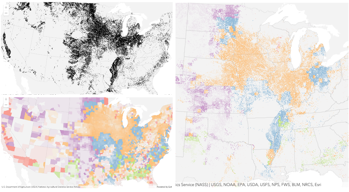
The following screenshots show feature and imagery layers on the left side on their own in the order they are drawn in the view. The imagery layer that contains land cover classification rasters.
The feature layer contains 2007 county crops data. The right image shows the result of layer blending where destination-in blendMode is set on the imagery layer. As you can see, the effect is
very different from the original layers. The blended result shows areas of cultivated crops only (where both imagery and feature layers overlap).
| Blend mode | Description |
|---|---|
| destination-over | Destination/background layer covers the top layer. The top layer is drawn underneath the destination layer. You'll see the top layer peek through wherever the background layer is transparent or has no data. |
| destination-atop | Destination/background layer is drawn only where it overlaps the top layer. The top layer is drawn underneath the background layer. You'll see the top layer peek through wherever the background layer is transparent or has no data. |
| destination-in | Destination/background layer is drawn only where it overlaps with the top layer. Everything else is made transparent. |
| destination-out | Destination/background layer is drawn where it doesn't overlap the top layer. Everything else is made transparent. |
| source-atop | Source/top layer is drawn only where it overlaps the background layer. You will see the background layer peek through where the source layer is transparent or has no data. |
| source-in | Source/top layer is drawn only where it overlaps with the background layer. Everything else is made transparent. |
| source-out | Source/top layer is drawn where it doesn't overlap the background layer. Everything else is made transparent. |
| xor | Top and background layers are made transparent where they overlap. Both layers are drawn normal everywhere else. |
Invert blend modes:
The following blend modes either invert or cancel out colors depending on colors of the background layer.
These blend modes look for variations between top and background layers.
For example, you can use difference or exclusion blend modes on two imagery layers of forest covers to visualize how forest covers changed from one year to another.
The invert blend mode can be used to turn any light basemap into a dark basemap to accommodate those who work in low-light conditions. The following screenshots show
how setting the invert blend mode set on a feature layer with a simple renderer turns the world Hillshade
into a dark themed basemap in no time.
| Blend mode | Description |
|---|---|
| difference | Subtracts the darker of the overlapping colors from the lighter color. When two pixels with the same value are subtracted, the result is black. Blending with black produces no change. Blending with white inverts the colors. This blending mode is useful for aligning layers with similar content. |
| exclusion | Similar to the difference blend mode, except that the resulting image is lighter overall. Overlapping areas with lighter color values are lightened, while darker overlapping color values become transparent. |
| minus | Subtracts colors of the top layer from colors of the background layer making the blend result darker. In the case of negative values, black is displayed. |
| invert | Inverts the background colors wherever the top and background layers overlap. The invert blend mode inverts the layer similar to a photographic negative. |
| reflect | This blend mode creates effects as if you added shiny objects or areas of light in the layer. Black pixels in the background layer are ignored as if they were transparent. |
- See also
- Default value
- "normal"
effect
Effect provides various filter functions that can be performed on the layer to achieve different visual effects similar to
how image filters work. This powerful capability allows you to apply css filter-like
functions to layers to create custom visual effects to enhance the cartographic quality of your maps. This is done by applying the desired
effect to the layer's effect property as a string or an array of objects to set scale dependent effects.
Notes
Set featureEffect property on a layer if different effects need to be applied features that meet or fail a specified filter. If all of the following four properties are applied, then they will be applied in this order: featureEffect, effect, opacity and blendMode.
Known Limitations
- The effect is not supported in 3D SceneViews.
- The effect cannot be applied to a layer with a heatmap renderer.
- The effect is not supported in layers with FeatureLayer.featureReduction of type
clusterenabled. - See print for known printing limitations.
Examples
// the following effect will be applied to the layer at all scales// brightness will be applied first, then hue-rotate followed by contrast// changing order of the effects will change the final resultlayer.effect = "brightness(5) hue-rotate(270deg) contrast(200%)";// set a scale dependent bloom effect on the layerlayer.effect = [ { scale: 36978595, value: "drop-shadow(3px, 3px, 4px)" }, { scale: 18489297, value: "drop-shadow(2px, 2px, 3px)" }, { scale: 4622324, value: "drop-shadow(1px, 1px, 2px)" }]; fullExtent
The full extent of the layer. By default, this is worldwide. This property may be used to set the extent of the view to match a layer's extent so that its features appear to fill the view. See the sample snippet below.
The fullExtent property is always null for GroupLayer.
Example
// Once the layer loads, set the view's extent to the layer's full extentlayer.when(function(){ view.extent = layer.fullExtent;}); initializationInclusionModeDefinition
Defines a set of named types and/or
entities
and relationships to be included in the layer.
If only a named type is specified, all instances of that type will be included
in the layer. Sublayers can be created for all named types
in the graph even if they have no instances specified in the member definition. The inclusion definition is not permanently dynamic.
It captures the data at the time of creation. For example, if generateAllSublayers is true and a new entity type is added to the knowledge graph,
that new entity type will not be added to the inclusion list. Similarly, if useAllData is true for a type, and a new record is added to
that type, the newly added record will not be automatically added to the inclusionList.
Constructor Only
This property is only supported when passed to the constructor on the first initialization of a link chart layer. Use WebLinkChart.addRecords() and WebLinkChart.removeRecords() to change the membership of the layer after initialization.
Examples
// constructing an inclusion list:// The exact record ids of each of the records of a specific named type (entity type or relationship type)// to include in the layer. In this case the layer will contain one recordconst layerInclusionMemberDefinition = new Map();layerInclusionMemberDefinition.set("{1A4W8G4-W52G-W89G-1W5G-J1R4S8H52H4S}",{id:"{1A4W8G4-W52G-W89G-1W5G-J1R4S8H52H4S}"})
 //The layerInclusionDefinition specifies whether to use all of the data in a named type or only the records// specified in the 'members' list. In this case we only want the records specified.const layerInclusionDefinition = {  useAllData: false, //only include instances in the member list  members: layerInclusionMemberDefinition};
// The namedTypeDefinition is a map of the typeName of each type to be included.// In this case we are only including the "Observation" entity type.// The layerInclusionDefinition specifies exactly which "Observation" entities to include in the layer.const namedTypeDefinition = new Map();namedTypeDefinition.set("Observation", layerInclusionDefinition);
// Specify if a sublayer should be generated for all named types.// If true, a sublayer will be created for all named types regardless of// whether they have a list of instances to include or not.// If there are no instances the sublayer will be empty. In this case we have set 'generateAllSubLayers' to false so the// layer will only contain sublayers for the named types (entity types or relationship types) that are specified// in the namedTypeDefinitions.// Also defines the collection of named types to include in the layer.const inclusionListDefinition = {  generateAllSublayers: false, //only create sublayers for the named types in the namedTypeDefinition  namedTypeDefinitions: namedTypeDefinition}
//examples of the initializationInclusionModeDefinition structure inside the LinkChartLayer
//the layer will only contain one sublayer (for 'supplier') and that sublayer will consist of one entity.{ generateAllSublayers: false, namedTypeDefinition:[{ key: "supplier", value:{ useAllData: false, members: [{ key: "{1A4W8G4-W52G-W89G-1W5G-J1R4S8H52H4S}", value: { id: "{1A4W8G4-W52G-W89G-1W5G-J1R4S8H52H4S}", } }] } }]}
// this layer will contain a sublayer for all named types in the graph// ('Observation', 'User', 'Species', "Observed", "Reviewed", "ObservedIn")// but only the 'Observation' sublayer will contain data.// The Observation sublayer will contain exactly one entity.{ generateAllSublayers: true, namedTypeDefinition:[{ key: "Observation", value:{ useAllData: false, members: [{ key: "{32CBD5CB-EE31-4714-B14F-57BFE36AE094}", value: { id: "{32CBD5CB-EE31-4714-B14F-57BFE36AE094}", } }] } }]}
// this layer will contain a sublayer for all named types in the graph// ('Observation', 'User', 'Species', "Observed", "Reviewed", "ObservedIn")// but only the 'Observation' sublayer will contain data.// the 'Observation' sublayer will contain all instance of the Observation entity type{ generateAllSublayers: true, namedTypeDefinition:[{ key: "Observation", value:{ useAllData: true } }]}
// A more complex example:{ //sublayers will only be created for the types listed generateAllSublayers: false, namedTypeDefinitions: { //include all `Species` entities that exist at the time the layer is created Species: { useAllData: true }, //include all `User` entities that exist at the time the layer is created User: { useAllData: true }, //include all only the specified `Observation` entities Observation: { useAllData:false, members: { "{941A7425-C45D-4940-A2E8-F3611973EC8A}": { id: "{941A7425-C45D-4940-A2E8-F3611973EC8A}" }, "{94DC1D53-4043-4D0B-8CF7-18B690414118}": { id: "{94DC1D53-4043-4D0B-8CF7-18B690414118}" }, //This entity has a fixed location so will remain in the same place regardless of the layout applied. //the other entities will move around it "{4E1D1ACE-6252-4BA4-B76E-CDEDFE9B0AB1}": { id: "{4E1D1ACE-6252-4BA4-B76E-CDEDFE9B0AB1}", }, "{559312DF-893C-44E2-AD86-BAA73CD49719}": { id: "{559312DF-893C-44E2-AD86-BAA73CD49719}" }, "{158A2D46-3EFF-4479-BC57-E6981FCB80B6}": { id: "{158A2D46-3EFF-4479-BC57-E6981FCB80B6}" }, "{40AD70FC-CD7D-4928-B555-38EA49675944}": { id: "{40AD70FC-CD7D-4928-B555-38EA49675944}" }, "{3A5B8F11-5971-4A46-99AC-F509CA59B517}": { id: "{3A5B8F11-5971-4A46-99AC-F509CA59B517}" } } }, //include all `Observed` relationships that exist at the time the layer is created Observed: { useAllData: true }, //include all `ObservedIn` relationships that exist at the time the layer is created ObservedIn: { useAllData: true } }} initializationLinkChartConfig
- Type
- InitializationLinkChartConfig | null | undefined
The default configuration options for a new link chart layer. This includes the layout and any layout settings for the initial view of the layer.
Constructor Only
This property is only supported when passed to the constructor on the first initialization of a link chart layer. Use WebLinkChart.applyLayout() to update the layout and layout settings after initialization.
layers
A collection of operational sublayers. Each sublayer represents an entity type or relationship type in the graph.
Each feature contained in each sublayer has a Geometry
that allows it to be rendered as a Graphic with spatial context on the View.
In GEOGRAPHIC layout mode, any spatial entities with Geometry will be drawn at their appropriate locations.
All non-spatial entities will be arrayed around the spatial entities they relate to.
In all other layouts, the geometry for each entity is its location on the link chart.
The location of specific instances can be set so that when the layout mode changes or the link chart is reloaded, they remain in the same
spot.
Features within the layer may also contain data Graphic.attributes that provide additional information that may be viewed in a Popup. These layers can also be queried and analyzed.
Example
//to access individual sublayers to add or modify properties such as the renderer, popups and labelsLinkChartLayer.layers.forEach((sublayer)=>{ sublayer.popupTemplate = new PopupTemplate({ title: "{common_name}", content: [{ type: "text", text: "Scientific Name: {name}" }] });}) listMode
- Type
- LayerListMode
Indicates how the layer should display in the Layer List component. The possible values are listed below.
| Value | Description |
|---|---|
| show | The layer is visible in the table of contents. |
| hide | The layer is hidden in the table of contents. |
| hide-children | If the layer is a GroupLayer, BuildingSceneLayer, KMLLayer, MapImageLayer, SubtypeGroupLayer, TileLayer, or WMSLayer, hide the children layers from the table of contents. |
- Default value
- "show"
loadError
The Error object returned if an error occurred while loading.
loadStatus
- Type
- "not-loaded" | "loading" | "failed" | "loaded"
Represents the status of a load() operation.
| Value | Description |
|---|---|
| not-loaded | The object's resources have not loaded. |
| loading | The object's resources are currently loading. |
| loaded | The object's resources have loaded without errors. |
| failed | The object's resources failed to load. See loadError for more details. |
- Default value
- "not-loaded"
loadWarnings
- Type
- any[]
A list of warnings which occurred while loading.
maxScale
- Type
- number
The maximum scale (most zoomed in) at which the layer is visible in the view.
If the map is zoomed in beyond this scale, the layer will not be visible.
A value of 0 means the layer does not have a maximum scale.
The maxScale value should always be smaller than the minScale value,
and greater than or equal to the service specification.
- Default value
- 0
Examples
// The layer will not be visible when the view is zoomed in beyond a scale of 1:1,000layer.maxScale = 1000;// The layer's visibility is not restricted to a maximum scale.layer.maxScale = 0; memberEntityTypes
- Type
- EntityType[]
- Since
- ArcGIS Maps SDK for JavaScript 4.32
The entity types included in the LinkChartLayer.
memberRelationshipTypes
- Type
- RelationshipType[]
- Since
- ArcGIS Maps SDK for JavaScript 4.32
The relationship types included in the LinkChartLayer.
minScale
- Type
- number
The minimum scale (most zoomed out) at which the layer is visible in the view.
If the map is zoomed out beyond this scale, the layer will not be visible.
A value of 0 means the layer does not have a minimum scale.
The minScale value should always be larger than the maxScale value,
and lesser than or equal to the service specification.
- Default value
- 0
Examples
// The layer will not be visible when the view is zoomed out beyond a scale of 1:3,000,000layer.minScale = 3000000;// The layer's visibility is not restricted to a minimum scale.layer.minScale = 0; opacity
- Type
- number
The opacity of the layer. This value can range between 1 and 0, where 0 is 100 percent
transparent and 1 is completely opaque.
Known Limitations
In a 3D SceneView, modifying opacity is not supported for DimensionLayer, GaussianSplatLayer, IntegratedMesh3DTilesLayer, IntegratedMeshLayer, LineOfSightLayer, PointCloudLayer, ViewshedLayer, and VoxelLayer.
- Default value
- 1
Example
// Makes the layer 50% transparentlayer.opacity = 0.5; parent
- Type
- Map | Basemap | Ground | GroupLayer | CatalogDynamicGroupLayer | CatalogLayer | null | undefined
The parent to which the layer belongs.
persistenceEnabled
- Type
- boolean
- Default value
- true
tables
All non-spatial entity type and relationship type
sublayers. They have the same structure as the spatial sublayers but the geometryType is null.
These layers can also be queried and analyzed.
All link chart sublayers are considered spatial because they have a diagram location.
uid
- Type
- string
- Since
- ArcGIS Maps SDK for JavaScript 4.33
An automatically generated unique identifier assigned to the instance. The unique id is generated each time the application is loaded.
visibilityTimeExtent
- Type
- TimeExtent | null | undefined
Specifies a fixed time extent during which a layer should be visible. This property can be used to configure a layer that does not have time values stored in an attribute field to work with time. Once configured, the TimeSlider widget will display the layer within the set time extent. In the case that only one of the TimeExtent.start or TimeExtent.end date values are available, the layer remains visible indefinitely in the direction where there is no time value.
Aerial imagery can capture seasonal variations in vegetation, water bodies, and land use patterns. For example, in agricultural regions, aerial imageries taken during different growing seasons provide insights into crop health and productivity. Defining a fixed time extent on imageries from specific time periods provides temporal context and facilitates focused analysis based on specific time periods or events.
visible
- Type
- boolean
Indicates if the layer is visible in the View. When false,
the layer may still be added to a Map
instance that is referenced in a view, but its features will not be visible in the view.
- Default value
- true
Example
// The layer is no longer visible in the viewlayer.visible = false;
// Watch for changes in the layer's visibility// and set the visibility of another layer when it changesreactiveUtils.watch(  () => layer.visible,  (visible) => {    if (visible) {      anotherLayer.visible = true;    } else {      anotherLayer.visible = false;    }  });
Methods
| Method | Signature | Class |
|---|---|---|
fromArcGISServerUrl inherited static | fromArcGISServerUrl(params: string | FromArcGISServerUrlParameters): Promise<Layer> | |
fromPortalItem inherited static | fromPortalItem(params: LayerFromPortalItemParameters): Promise<Layer> | |
applyNewLinkChartLayout(): Promise<void> | | |
cancelLoad inherited | cancelLoad(): this | |
createLayerView inherited | createLayerView<T extends LayerView = LayerView>(view: View<T>, options?: AbortOptions): Promise<T> | |
destroy inherited | destroy(): void | |
emit inherited | emit<Type extends EventNames<this>>(type: Type, event?: this["@eventTypes"][Type]): boolean | |
fetchAttributionData inherited | fetchAttributionData(): Promise<any> | |
hasEventListener inherited | hasEventListener<Type extends EventNames<this>>(type: Type): boolean | |
isFulfilled inherited | isFulfilled(): boolean | |
isRejected inherited | isRejected(): boolean | |
isResolved inherited | isResolved(): boolean | |
load inherited | load(options?: AbortOptions | null | undefined): Promise<this> | |
loadLayerAssumingLocalCache(): void | | |
on inherited | on<Type extends EventNames<this>>(type: Type, listener: EventedCallback<this["@eventTypes"][Type]>): ResourceHandle | |
when inherited | when<TResult1 = this, TResult2 = never>(onFulfilled?: OnFulfilledCallback<this, TResult1> | null | undefined, onRejected?: OnRejectedCallback<TResult2> | null | undefined): Promise<TResult1 | TResult2> |
fromArcGISServerUrl
- Signature
-
fromArcGISServerUrl (params: string | FromArcGISServerUrlParameters): Promise<Layer>
Creates a new layer instance from an ArcGIS Server URL. Depending on the URL, the returned layer type may be a BuildingSceneLayer, CatalogLayer, ElevationLayer, FeatureLayer, GroupLayer, ImageryLayer, ImageryTileLayer, IntegratedMeshLayer, KnowledgeGraphLayer, MapImageLayer, OrientedImageryLayer, PointCloudLayer, SceneLayer, StreamLayer, SubtypeGroupLayer, TileLayer, or VideoLayer.
This is useful when you work with various ArcGIS Server URLs, but you don't necessarily know which layer type(s) they create. This method creates the appropriate layer type for you. In case of a feature service or a scene service, when the URL points to the service and the service has multiple layers, the returned promise will resolve to a GroupLayer.
Beginning with version 4.17, it is possible to load tables from hosted feature services.
This only applies to feature layers, and will successfully load if FeatureLayer.isTable returns true.
The following table details what is returned when loading specific URL types.
| URL | Returns |
|---|---|
| Feature service with one layer | FeatureLayer where FeatureLayer.isTable returns false. |
| Feature service with one table | FeatureLayer where FeatureLayer.isTable returns true. |
| Feature service with more than one layer(s)/table(s) | GroupLayer with layers and tables. |
| Layers with type other than "Feature Layer" are discarded, e.g. Utility Network Layers | N/A |
- See also
Parameters
| Parameter | Type | Description | Required |
|---|---|---|---|
| params | Input parameters for creating the layer. | |
Examples
// This snippet shows how to add a feature layer from an ArcGIS Server URL// Get an ArcGIS Server URL from a custom functionconst arcgisUrl = getLayerUrl();
Layer.fromArcGISServerUrl({  url: arcgisUrl,  properties: {    // set any layer properties here    popupTemplate: new PopupTemplate()  }}).then(function(layer){  // add the layer to the map  map.add(layer);});
// This snippet shows how to add a table from an ArcGIS Server URL// Get an ArcGIS Server URL from a custom functionconst arcgisUrl = getLayerUrl();
Layer.fromArcGISServerUrl({ url: arcgisUrl}).then(function(layer){ // Load the table before it can be used layer.load().then(function() { // Check that it is the right type if (layer.isTable) { // Add table to map's tables collection map.tables.add(layer); } });}); fromPortalItem
- Signature
-
fromPortalItem (params: LayerFromPortalItemParameters): Promise<Layer>
Creates a new layer instance of the appropriate layer class from an ArcGIS Online or ArcGIS Enterprise portal item. If the item points to a feature service with multiple layers, then a GroupLayer is created. If the item points to a service with a single layer, then it resolves to a layer of the same type of class as the service.
Note
- At version 4.29, MediaLayer can be loaded from portal items.
- At version 4.28, GroupLayer and OrientedImageryLayer can be loaded from portal items.
- At version 4.25, CSVLayer and GeoJSONLayer can be loaded from CSV and GeoJSON portal items respectively.
- At version 4.17, it is possible to load tables from feature service items hosted in ArcGIS Online and ArcGIS Enterprise.
This only applies to feature layers, and will successfully load
if FeatureLayer.isTable returns
true.
The following table details what is returned when loading specific item types.
| Item(s) | Returns |
|---|---|
| Feature service with one layer | FeatureLayer where FeatureLayer.isTable returns false. |
| Feature service with one table | FeatureLayer where FeatureLayer.isTable returns true. |
| Feature service with more than one layer(s)/table(s) | GroupLayer with layers and tables. |
| Feature collection with one layer | FeatureLayer where FeatureLayer.isTable returns false. |
| Feature collection with one table | FeatureLayer where FeatureLayer.isTable returns true. |
| Feature collection with more than one layer(s)/table(s) | GroupLayer with layers and tables. |
Known Limitations
- This method does not currently work with OGCFeatureServer portal items.
Parameters
| Parameter | Type | Description | Required |
|---|---|---|---|
| params | The parameters for loading the portal item. | |
Examples
// Create a layer from a specified portal item and add to the mapLayer.fromPortalItem({ portalItem: { // autocasts new PortalItem() id: "8444e275037549c1acab02d2626daaee" }}).then(function(layer){ // add the layer to the map map.add(layer);});// Create a table from a specified portal item and add it to the map's tables collectionLayer.fromPortalItem({ portalItem: { // autocasts new PortalItem() id: "123f4410054b43d7a0bacc1533ceb8dc" // This is a hosted table stored in a feature service }}).then(function(layer) { // Necessary to load the table in order for it to be read correctly layer.load().then(function() { // Confirm this reads as a table if (layer.isTable) { // Add the new table to the map's table collection map.tables.add(layer); } });}); cancelLoad
- Signature
-
cancelLoad (): this
Cancels a load() operation if it is already in progress.
- Returns
- this
createLayerView
- Signature
-
createLayerView <T extends LayerView = LayerView>(view: View<T>, options?: AbortOptions): Promise<T>
Called by the views, such as MapView and SceneView, when the layer is added to the Map.layers collection and a layer view must be created for it. This method is used internally and there is no use case for invoking it directly.
- See also
Parameters
| Parameter | Type | Description | Required |
|---|---|---|---|
| view | The parent view. | | |
| options | An object specifying additional options. See the object specification table below for the required properties of this object. | |
destroy
- Signature
-
destroy (): void
Destroys the layer and any associated resources (including its portalItem, if it is a property on the layer). The layer can no longer be used once it has been destroyed.
The destroyed layer will be removed from its parent object like Map, WebMap, WebScene, Basemap, Ground, or GroupLayer.
- Returns
- void
emit
- Signature
-
emit <Type extends EventNames<this>>(type: Type, event?: this["@eventTypes"][Type]): boolean
- Type parameters
- <Type extends EventNames<this>>
Emits an event on the instance. This method should only be used when creating subclasses of this class.
hasEventListener
- Signature
-
hasEventListener <Type extends EventNames<this>>(type: Type): boolean
- Type parameters
- <Type extends EventNames<this>>
Indicates whether there is an event listener on the instance that matches the provided event name.
Parameters
| Parameter | Type | Description | Required |
|---|---|---|---|
| type | Type | The name of the event. | |
- Returns
- boolean
Returns true if the class supports the input event.
isFulfilled
- Signature
-
isFulfilled (): boolean
isFulfilled() may be used to verify if creating an instance of the class is fulfilled (either resolved or rejected).
If it is fulfilled, true will be returned.
- Returns
- boolean
Indicates whether creating an instance of the class has been fulfilled (either resolved or rejected).
isRejected
- Signature
-
isRejected (): boolean
isRejected() may be used to verify if creating an instance of the class is rejected.
If it is rejected, true will be returned.
- Returns
- boolean
Indicates whether creating an instance of the class has been rejected.
isResolved
- Signature
-
isResolved (): boolean
isResolved() may be used to verify if creating an instance of the class is resolved.
If it is resolved, true will be returned.
- Returns
- boolean
Indicates whether creating an instance of the class has been resolved.
load
- Signature
-
load (options?: AbortOptions | null | undefined): Promise<this>
Loads the resources referenced by this class. This method automatically executes for a View and all of the resources it references in Map if the view is constructed with a map instance.
This method must be called by the developer when accessing a resource that will not be loaded in a View.
The load() method only triggers the loading of the resource the first time it is called. The subsequent calls return the same promise.
It's possible to provide a signal to stop being interested into a Loadable instance load status.
When the signal is aborted, the instance does not stop its loading process, only cancelLoad() can abort it.
loadLayerAssumingLocalCache
- Signature
-
loadLayerAssumingLocalCache (): void
Loads layer assuming that data for all of the members defined in the initializationInclusionModeDefinition is already loaded into local storage. This will optimize layer load times.
- Returns
- void
on
- Signature
-
on <Type extends EventNames<this>>(type: Type, listener: EventedCallback<this["@eventTypes"][Type]>): ResourceHandle
- Type parameters
- <Type extends EventNames<this>>
Registers an event handler on the instance. Call this method to hook an event with a listener.
Parameters
| Parameter | Type | Description | Required |
|---|---|---|---|
| type | Type | An event or an array of events to listen for. | |
| listener | EventedCallback<this["@eventTypes"][Type]> | The function to call when the event fires. | |
- Returns
- ResourceHandle
Returns an event handler with a
remove()method that should be called to stop listening for the event(s).Property Type Description remove Function When called, removes the listener from the event.
Example
view.on("click", function(event){ // event is the event handle returned after the event fires. console.log(event.mapPoint);}); when
- Signature
-
when <TResult1 = this, TResult2 = never>(onFulfilled?: OnFulfilledCallback<this, TResult1> | null | undefined, onRejected?: OnRejectedCallback<TResult2> | null | undefined): Promise<TResult1 | TResult2>
when() may be leveraged once an instance of the class is created. This method takes two input parameters: an onFulfilled function and an onRejected function.
The onFulfilled executes when the instance of the class loads. The
onRejected executes if the instance of the class fails to load.
Parameters
| Parameter | Type | Description | Required |
|---|---|---|---|
| onFulfilled | OnFulfilledCallback<this, TResult1> | null | undefined | The function to call when the promise resolves. | |
| onRejected | The function to execute when the promise fails. | |
- Returns
- Promise<TResult1 | TResult2>
Returns a new promise for the result of
onFulfilledthat may be used to chain additional functions.
Example
// Although this example uses MapView, any class instance that is a promise may use when() in the same waylet view = new MapView();view.when(function(){ // This function will execute once the promise is resolved}, function(error){ // This function will execute if the promise is rejected due to an error});Events
| Name | Type |
|---|---|
layerview-create inherited | |
layerview-create-error inherited | |
layerview-destroy inherited |
layerview-create
layerview-create: CustomEvent<LayerLayerviewCreateEvent> Fires after the layer's LayerView is created and rendered in a view.
- See also
Example
// This function will fire each time a layer view is created for this// particular view.layer.on("layerview-create", function(event){ // The LayerView for the layer that emitted this event event.layerView;}); layerview-create-error
layerview-create-error: CustomEvent<LayerLayerviewCreateErrorEvent> Fires when an error emits during the creation of a LayerView after a layer has been added to the map.
- See also
Example
// This function fires when an error occurs during the creation of the layer's layerviewlayer.on("layerview-create-error", function(event) { console.error("LayerView failed to create for layer with the id: ", layer.id, " in this view: ", event.view);}); layerview-destroy
layerview-destroy: CustomEvent<LayerLayerviewDestroyEvent> Fires after the layer's LayerView is destroyed and no longer renders in a view.
Type definitions
InitializationLinkChartConfig
Defines the initial layout for the link chart and any layout settings for newly created link chart layers.
layoutMode
- Type
- LayoutMode | undefined
The layout mode to be applied by default. The system default is organic-standard.
doNotRecalculateLayout
By default, the layout algorithm always runs on link charts when they are first created.
If all diagram locations are set for every entity in the inclusion definition, this property can be set to true which skips the layout algorithm step and increases the performance of larger link charts.
layoutSettings
- Type
- LayoutSettings | undefined
Additional layout options for the default layout configuration.