import Mesh from "@arcgis/core/geometry/Mesh.js";const Mesh = await $arcgis.import("@arcgis/core/geometry/Mesh.js");- Since
- ArcGIS Maps SDK for JavaScript 4.7
A mesh is a general, client-side 3D Geometry type composed of vertices with attributes. The vertices include geographic position, normals that affect lighting/shading and UV coordinates that can be used to map images to the mesh. Vertices are combined into 3D primitives to render the mesh in the scene (only triangle primitives are currently supported).
Mesh geometries can have an intrinsic material that determines how it is being displayed. Similar to 3D objects in scene layers, mesh geometries are symbolized with a MeshSymbol3D symbol containing a FillSymbol3DLayer.
To support multiple materials (as is often the case for complex 3D models), meshes may define components that define a material for a specific region in the mesh. In addition to supporting multiple materials, components can also reuse vertices that would otherwise be duplicated to form triangles.
Meshes are loadable since 4.27. In particular when meshes come from remote services like through SceneLayer.queryFeatures(), then the contents of the mesh needs to be loaded asynchronously through the load() method before vertexAttributes, extent, components, etc. are available.
Meshes represent fully georeferenced 3D geometry and care needs to be taken when importing mesh data.
Read More
It is typical for modern 3D GIS workflows that 3D geometry data be represented by 3D models, which can be stored in different file formats like glTF, OBJ, FBX, IFC, etc. These models can come from different sources, such as 3D modeling software like SketchUp or Blender, CAD software like Revit, or even custom mesh generation code.
While some of the software may work in a georeferenced space and some of the file formats, such as IFC, may be georeferenced, much of the software and most of the model file formats are not georeferenced. This presents the challenge of expressing different georeferencing scenarios while maintaining a fast and efficient experience when displaying and editing 3D model content. In the Maps SDK we strive to strike a good balance between allowing our users to work with different scenarios while preventing situations in which good display and editing experience cannot be provided.
Mesh API
The entry point for representing 3D models in the Maps SDK is the Mesh. We refer to the API reference for details on mesh components, MeshComponent.material and how to create meshes. This guide is concerned with georeferencing meshes.
A mesh represents a georeferenced 3D model in the Maps SDK. In order to fully georeference meshes three things are needed:
- Spatial reference
- Location of the mesh in that spatial reference. We call this the origin.
- The coordinate system in which mesh vertices are provided. We call it the vertex space.
Given these three things, meshes can be fully georeferenced. However, for certain configurations of spatial reference, mesh vertex space and viewing mode, costly projection may be required. Because that would greatly affect display and editing performance, we decided to not display or allow editing in those cases. Please see the limitations section for an overview of these restrictions.
The spatial reference of the mesh is provided with its construction. When using one of the create functions, such as createFromGLTF(), the spatial reference will be taken from the provided location.
Mesh vertex spaces
The origin and spatial reference of a mesh provide georeferencing, but only for the origin. A mesh is composed of vertices, and they may exist in different coordinate systems depending on the data source. Hence, to fully georeference the mesh, it's crucial to define the coordinate system associated with the mesh vertices. The mesh vertex space property was introduced to address this need. This property specifies the meaning of the mesh vertex coordinates, ensuring that the entire mesh can be correctly georeferenced.
Mesh local vertex space
Most popular 3D model formats, such as glTF, are not georeferenced and represent the mesh vertex coordinates in a plain local cartesian space with some length unit (e.g. meters for glTF). The coordinate (0,0,0) is the origin. We call this coordinate system "local" and represent it using the MeshLocalVertexSpace. The units in this vertex space are always "meters".
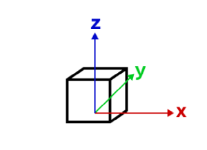
local vertex space
Georeferencing local coordinates is done by "putting them on the map" using a georeferenced cartesian reference frame. This frame is found by using the local tangent plane at the georeferenced origin of the mesh. When the spatial reference uses a geographic coordinate system (GCS) or Web Mercator, the tangent plane is aligned such that the local Y tangent vector is always pointing to the north pole resulting in the east, north, up (ENU) frame.
Currently we use the tangent plane of the sphere even for ellipsoidal geographic coordinate systems. This is a simplification we use as we render on a perfect sphere in global viewing mode.

local vertex space on GCS or Web Mercator (ENU)
A local vertex space with a spatial reference which is a GCS or Web Mercator is efficient to work with as the tangent plane is easy to find and we can simply move the vertices to its georeferenced location using efficient linear transformations. This comes at the cost of an approximation error between the tangent plane and the actual surface. Consequently for larger models, this error increases while it decreases as the models get smaller.
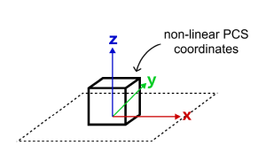
There is an important element to consider when a mesh is created with a local vertex space (e.g. by creating it from a glTF) and displayed in local viewing mode where a projected coordinate system (PCS) is used:
The projection introduces a warping and distortion of the space in order to allow mapping of surface coordinates to a plane. This produces a mismatch between the linear coordinates of the local vertex space and the warped, non-linear coordinates of the underlying spatial reference. While steps along a line in the local vertex space are of same length, steps along a line in the underlying spatial reference are not. This means that measuring the same line in local space and the underlying spatial reference will produce different measurements. This difference further depends on the origin location of the mesh. It is important to realize that this scenario cannot be used when correct georeferencing is required.
Mesh georeferenced vertex spaces
The georeferenced vertex space indicates that mesh vertices are already projected and that their coordinates are in the spatial reference of the mesh. If an MeshGeoreferencedVertexSpace.origin is provided, those vertex coordinates are interpreted as offsets relative to the origin. Otherwise, the coordinates are interpreted as absolute.
georeferenced vertex space on PCS
Display and editing are efficient for meshes with a georeferenced vertex space and when the spatial reference is a projected coordinate system and matches the spatial reference of the view. This is because in those cases, manipulations like moving a mesh can be expressed as linear transformations.
The effect of viewing modes
We will not display or allow edits for configurations where efficient display or editing is not possible due to costly reprojections being required. It is important to realize that the SceneView.viewingMode defines the spatial reference in which the data is displayed and hence has a direct effect on which vertex space and spatial reference combination of meshes can be done efficiently. This means that, depending on the viewing mode, display and editing of meshes with certain combinations of vertex space and spatial reference are not supported. See limitations for an overview.
We established that for mesh spatial references which use a geographic coordinate system (or Web Mercator) and a local vertex space, display and editing can be done efficiently. That is true for "global" viewing mode, where the view uses a geographic coordinate system (or Web Mercator) for display.
Meshes with a georeferenced vertex space and a spatial reference using a projected coordinate system (PCS) can be displayed and edited efficiently in a view using the "local" viewing mode and when the view has the same spatial reference as the mesh.
Web Mercator
Web Mercator is a spatial reference with a projected coordinate system and the de facto standard for web mapping applications. This is due to its suitability for efficient map tiling. Even though it uses a projected coordinate system, we still support using Web Mercator in global viewing mode. This is because of its importance for web mapping and also because projecting Web Mercator on the globe cancels out the strong distortions near the poles. It is the only PCS based spatial reference we support in global viewing mode.
Web Mercator support for global viewing mode naturally extends to supporting efficient display and editing for meshes with a Web Mercator spatial reference and a local vertex space, even though it is based on a projected coordinate system. Since Web Mercator is a spatial reference based on a PCS, we also support efficient display and editing for Web Mercator with meshes using a georeferenced vertex space. Web Mercator is the only exception to the rule of only meshes with a spatial reference with a geographic coordinate system can be supported in global viewing mode.
Limitations
- See Scene Layers in regards to limitations on display and editing for mesh features.
Troubleshooting mesh georeferencing
If meshes are not being displayed, then chances are that this is due to a configuration which the API does not support for display and editing.
- First check the SceneView.viewingMode, spatial reference and vertex space of the problematic mesh and consult the console of the JavaScript debugger. If the API rejects display of meshes, a warning message is printed.
- If it is determined that an unsupported configuration is used, consider switching the SceneView.viewingMode in your application.
- If there is no other option, consider changing the data by switching to a supported spatial reference for the required SceneView.viewingMode or by converting the mesh vertex data between local and georeferenced vertex space.
- If meshes are displayed wrongly, then this could also be due to the vertex space not being correct. If applications export geometry with georeferenced coordinates as OBJ file for example, then one would need to use the
"georeferenced"vertex space.
Create simple mesh geometry primitives
The mesh geometry class has a number of convenience functions to create simple primitive shapes. These shapes can help you get started with understanding mesh geometries.
// Create a box mesh geometrylet mesh = Mesh.createBox(location, {  size: {    width: 100,    height: 50,    depth: 50  },  material: {    color: "red"  }});
// Create a graphic and add it to the viewlet graphic = new Graphic({  geometry: mesh,  symbol: {    type: "mesh-3d",    symbolLayers: [ { type: "fill" } ]  }});
view.graphics.add(graphic);
Create mesh geometries manually
Mesh geometries can be manually created by specifying vertexAttributes and components like in the following example:
// Create a mesh geometry representing a pyramidlet pyramidMesh = new Mesh({  vertexAttributes: {    // vertex positions for the Louvre pyramid, Paris    position: [      // vertex 0 - base of the pyramid, south      2.336006, 48.860818, 0,
      // vertex 1 - base of the pyramid, east      2.336172, 48.861114, 0,
      // vertex 2 - base of the pyramid, north      2.335724, 48.861229, 0,
      // vertex 3 - base of the pyramid, west      2.335563, 48.860922, 0,
      // vertex 4 - top of the pyramid      2.335896, 48.861024, 21    ]  },  // Add a single component with faces that index the vertices  // so we only need to define them once  components: [    {      faces: [        0, 4, 3,        0, 1, 4,        1, 2, 4,        2, 3, 4      ]    }  ],  // specify a spatial reference if the position of the vertices is not in WGS84});
// add the mesh geometry to a graphiclet graphic = new Graphic({  geometry: pyramidMesh,  symbol: {    type: "mesh-3d",    symbolLayers: [ { type: "fill" } ]  }});
view.graphics.add(graphic);
Note: Starting with version 4.11 autocasting is no longer supported for Mesh geometry.
Constructors
Constructor
Parameters
| Parameter | Type | Description | Required |
|---|---|---|---|
| properties | | |
Properties
| Property | Type | Class |
|---|---|---|
cache readonly inherited | ||
MeshComponent[] | null | undefined | | |
declaredClass readonly inherited | ||
extent readonly | | |
hasM inherited | ||
hasZ inherited | ||
loadError readonly inherited | ||
loadStatus readonly inherited | "not-loaded" | "loading" | "failed" | "loaded" | |
loadWarnings readonly inherited | any[] | |
origin readonly | | |
spatialReference inherited | ||
| | ||
type readonly | "mesh" | |
| | ||
vertexSpace readonly | |
components
- Type
- MeshComponent[] | null | undefined
An array of mesh components that can be used to apply materials to different regions of the same mesh. There are three common usage patterns for components.
- Specify a material for the whole mesh. In this case, use a single
component with only a material (leaving faces as
null). - Reuse vertex attributes. When modeling continuous surfaces, it can be convenient to only specify vertices once and then simply refer to them. In this case, use a single component with faces set to index the vertex attributes that form triangles.
- Specify multiple materials for the same mesh. In this case, use multiple components with faces that determine to which region of the mesh the material of the component applies.
extent
- Type
- Extent
The 3D extent of the mesh geometry. The extent is computed from the vertex positions stored in the vertexAttributes. The 3D extent is computed on-demand and cached. If you modify the vertexAttributes manually, then you must call vertexAttributesChanged() to make sure the extent will be recomputed.
hasZ
- Type
- boolean
Indicates if the geometry has z-values (elevation).
Z-values defined in a geographic or metric coordinate system are expressed in meters. However, in local scenes that use a projected coordinate system, vertical units are assumed to be the same as the horizontal units specified by the service.
- Default value
- false
loadError
The Error object returned if an error occurred while loading.
loadStatus
- Type
- "not-loaded" | "loading" | "failed" | "loaded"
Represents the status of a load() operation.
| Value | Description |
|---|---|
| not-loaded | The object's resources have not loaded. |
| loading | The object's resources are currently loading. |
| loaded | The object's resources have loaded without errors. |
| failed | The object's resources failed to load. See loadError for more details. |
- Default value
- "not-loaded"
loadWarnings
- Type
- any[]
A list of warnings which occurred while loading.
origin
- Type
- Point
- Since
- ArcGIS Maps SDK for JavaScript 4.30
The origin of the mesh. This corresponds to the vertex space origin for relative vertex spaces. For absolute vertex spaces, the origin is at the bottom of the mesh.
spatialReference
- Type
- SpatialReference
The spatial reference of the geometry.
- Default value
- SpatialReference.WGS84 // wkid: 4326
transform
- Type
- MeshTransform | null | undefined
Additional local transformation of the mesh vertices. The transform is ignored if the [vertexSpace)(#vertexSpace) is of type georeferenced and does not specify an MeshGeoreferencedVertexSpace.origin.
vertexAttributes
- Type
- MeshVertexAttributes
Object describing the attributes of each vertex of the mesh. Vertex attributes are flat numerical arrays that describe the position (mandatory), normal (used for lighting calculations and shading) and UV (used for mapping material images to the mesh surface) for each vertex.
Vertex attributes can be addressed by indices specified in the components MeshComponent.faces property. If the mesh does not contain any components, or if a component does not specify any faces, then the vertex attributes are interpreted as if each consecutive vertex triple makes up a triangle.
Example
let mesh = new Mesh({ spatialReference: SpatialReference.WebMercator });
// Specify vertices for two triangles that make up a square// around a provided point. UV coordinates are set up to cover the square// from (0, 0) to (1, 1) from corner to corner.mesh.vertexAttributes = {  position: [    pt.x - 10, pt.y - 10, 100,    pt.x + 10, pt.y - 10, 100,    pt.x + 10, pt.y + 10, 100,
    pt.x - 10, pt.y - 10, 100,    pt.x + 10, pt.y + 10, 100,    pt.x - 10, pt.y + 10, 100  ],  uv: [    0, 0,    1, 0,    1, 1,
    0, 0,    1, 1,    0, 1  ]};
vertexSpace
- Type
- MeshVertexSpaceUnion
The vertex space of the mesh. See mesh API for details.
Methods
| Method | Signature | Class |
|---|---|---|
createBox static | createBox(location: Point, parameters?: CreateBoxParameters): Mesh | |
createCylinder static | createCylinder(location: Point, parameters?: CreateCylinderParameters): Mesh | |
createFromGLTF static | createFromGLTF(location: Point, url: string, parameters?: CreateFromGLTFParameters): Promise<Mesh> | |
createFromPolygon static | createFromPolygon(polygon: Polygon, parameters?: CreateFromPolygonParameters): Mesh | |
createPlane static | createPlane(location: Point, parameters?: CreatePlaneParameters): Mesh | |
createSphere static | createSphere(location: Point, parameters?: CreateSphereParameters): Mesh | |
fromJSON inherited static | fromJSON(json: any): any | |
addComponent(component: MeshComponentProperties): void | | |
cancelLoad inherited | cancelLoad(): this | |
centerAt(location: Point, parameters?: CenterAtParameters): this | | |
clone(): this | | |
isFulfilled inherited | isFulfilled(): boolean | |
isRejected inherited | isRejected(): boolean | |
isResolved inherited | isResolved(): boolean | |
load inherited | load(options?: AbortOptions | null | undefined): Promise<this> | |
offset(dx: number, dy: number, dz: number): this | | |
removeComponent(component: MeshComponent): void | | |
rotate(angleX: number, angleY: number, angleZ: number, parameters?: RotateParameters): this | | |
scale(factor: number, parameters?: ScaleParameters): this | | |
toBinaryGLTF(options?: ExportGLTFOptions): Promise<ArrayBuffer> | | |
toJSON inherited | toJSON(): any | |
vertexAttributesChanged(): void | | |
when inherited | when<TResult1 = this, TResult2 = never>(onFulfilled?: OnFulfilledCallback<this, TResult1> | null | undefined, onRejected?: OnRejectedCallback<TResult2> | null | undefined): Promise<TResult1 | TResult2> |
createBox
- Signature
-
createBox (location: Point, parameters?: CreateBoxParameters): Mesh
Creates a mesh representing a box. The spatial reference of the resulting mesh is the same as the location where it is placed.
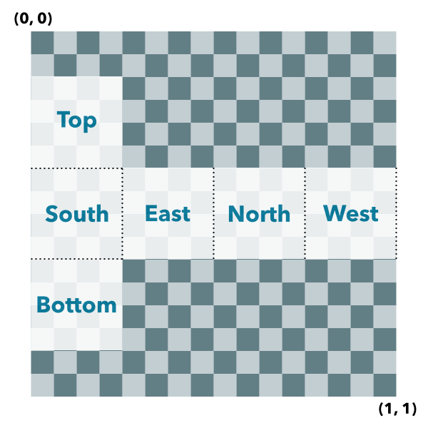
Box UV coordinate space
The box geometry will have UV coordinates generated according to the following scheme:
Parameters
| Parameter | Type | Description | Required |
|---|---|---|---|
| location | The location bottom center of the box. | | |
| parameters | Parameters to configure the box creation. | |
- Returns
- Mesh
The resulting mesh.
Examples
let mesh = Mesh.createBox(point, { size: { width: 10, height: 100, depth: 20 }, material: { color: "green" }});let mesh = Mesh.createBox(point, { imageFace: "top", material: { colorTexture: new MeshTexture({ url: "./url-to-image.png" }) }}); createCylinder
- Signature
-
createCylinder (location: Point, parameters?: CreateCylinderParameters): Mesh
Creates a mesh representing a cylinder. The spatial reference of the resulting mesh is the same as the location where it is placed.
Cylinder UV coordinate space
The cylinder geometry will have UV coordinates generated according to the following scheme (example is shown for 8 vertices cylinder):
Parameters
| Parameter | Type | Description | Required |
|---|---|---|---|
| location | The location of the bottom center of the cylinder. | | |
| parameters | Parameters to configure the cylinder creation. | |
- Returns
- Mesh
The resulting mesh.
createFromGLTF
- Signature
-
createFromGLTF (location: Point, url: string, parameters?: CreateFromGLTFParameters): Promise<Mesh>
- Since
- ArcGIS Maps SDK for JavaScript 4.11
Creates a new mesh geometry from a glTF model referenced by the url parameter.
The spatial reference of the resulting mesh is the same as the spatial reference of the location parameter. For
more information on the supported glTF features you can read the
Visualizing points with 3D symbols guide topic. Animations are currently unsupported.
Parameters
| Parameter | Type | Description | Required |
|---|---|---|---|
| location | The location of the origin of the model. If the location does not
contain a z-value, z is assumed to be | | |
| url | The URL of the glTF model. The URL should point to a glTF file (.gltf or .glb) which can reference additional binary (.bin) and image files (.jpg, .png). | | |
| parameters | Parameters to configure the mesh from glTF creation. | |
createFromPolygon
- Signature
-
createFromPolygon (polygon: Polygon, parameters?: CreateFromPolygonParameters): Mesh
Creates a new mesh geometry from a polygon geometry. The resulting mesh contains only
a position vertex attribute and a single component with faces. The default shading will be
set to flat. The spatial reference of the resulting mesh is the same
as the input polygon. The resulting mesh will not contain any UV nor normal vertex attributes.
Parameters
| Parameter | Type | Description | Required |
|---|---|---|---|
| polygon | The input polygon. | | |
| parameters | Optional parameters. | |
- Returns
- Mesh
A new mesh representing the triangulated polygon.
createPlane
- Signature
-
createPlane (location: Point, parameters?: CreatePlaneParameters): Mesh
Creates a mesh representing a plane. The spatial reference of the resulting mesh is the same as the location where it is placed. A plane consists of two triangles and may be conveniently oriented at creation time.
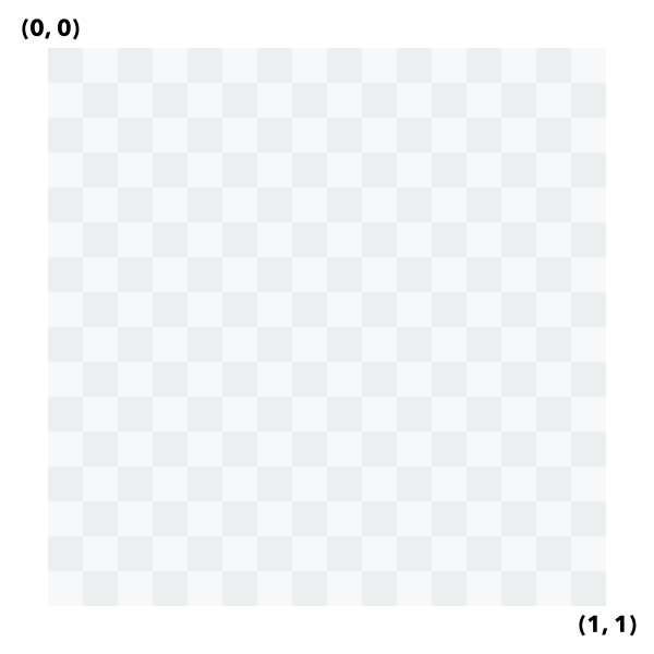
Plane UV coordinate space
The plane geometry will have UV coordinates generated according to the following scheme:
Parameters
| Parameter | Type | Description | Required |
|---|---|---|---|
| location | The location of the bottom center of the plane. | | |
| parameters | Parameters to configure the plane creation. | |
- Returns
- Mesh
The resulting mesh.
createSphere
- Signature
-
createSphere (location: Point, parameters?: CreateSphereParameters): Mesh
Creates a mesh representing a sphere. The spatial reference of the resulting mesh is the same as the location where it is placed.
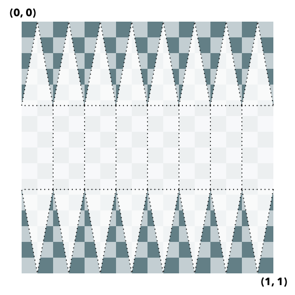
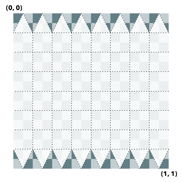
Sphere UV coordinate space
The sphere geometry will have UV coordinates generated according to the following scheme (example is shown for 8x8 vertices sphere):
Parameters
| Parameter | Type | Description | Required |
|---|---|---|---|
| location | The location of the bottom center of the sphere. | | |
| parameters | Parameters to configure the sphere creation. | |
- Returns
- Mesh
The resulting mesh.
fromJSON
- Signature
-
fromJSON (json: any): any
Creates a new instance of this class and initializes it with values from a JSON object
generated from an ArcGIS product. The object passed into the input json
parameter often comes from a response to a query operation in the REST API or a
toJSON()
method from another ArcGIS product. See the Using fromJSON()
topic in the Guide for details and examples of when and how to use this function.
Parameters
| Parameter | Type | Description | Required |
|---|---|---|---|
| json | A JSON representation of the instance in the ArcGIS format. See the ArcGIS REST API documentation for examples of the structure of various input JSON objects. | |
- Returns
- any
Returns a new instance of this class.
addComponent
- Signature
-
addComponent (component: MeshComponentProperties): void
Adds a component to the mesh.
Parameters
| Parameter | Type | Description | Required |
|---|---|---|---|
| component | The component to add. | |
- Returns
- void
cancelLoad
- Signature
-
cancelLoad (): this
Cancels a load() operation if it is already in progress.
- Returns
- this
centerAt
- Signature
-
centerAt (location: Point, parameters?: CenterAtParameters): this
Centers the mesh at the specified location without changing its scale. This effectively adjusts the mesh origin and mesh vertices such that vertices are given relative to the new location and the new location is the new origin. The effective georeferenced vertex positions will not change.
The mesh will be modified in place. To modify a copy of the mesh instead, use clone() before calling centerAt().
Parameters
| Parameter | Type | Description | Required |
|---|---|---|---|
| location | The location at which to center the mesh. | | |
| parameters | Additional parameters. | |
- Returns
- this
The modified mesh.
clone
- Signature
-
clone (): this
Creates a deep clone of the Mesh object.
- Returns
- this
A new instance of a Mesh object equal to the object used to call
.clone().
isFulfilled
- Signature
-
isFulfilled (): boolean
isFulfilled() may be used to verify if creating an instance of the class is fulfilled (either resolved or rejected).
If it is fulfilled, true will be returned.
- Returns
- boolean
Indicates whether creating an instance of the class has been fulfilled (either resolved or rejected).
isRejected
- Signature
-
isRejected (): boolean
isRejected() may be used to verify if creating an instance of the class is rejected.
If it is rejected, true will be returned.
- Returns
- boolean
Indicates whether creating an instance of the class has been rejected.
isResolved
- Signature
-
isResolved (): boolean
isResolved() may be used to verify if creating an instance of the class is resolved.
If it is resolved, true will be returned.
- Returns
- boolean
Indicates whether creating an instance of the class has been resolved.
load
- Signature
-
load (options?: AbortOptions | null | undefined): Promise<this>
Loads the resources referenced by this class. This method automatically executes for a View and all of the resources it references in Map if the view is constructed with a map instance.
This method must be called by the developer when accessing a resource that will not be loaded in a View.
The load() method only triggers the loading of the resource the first time it is called. The subsequent calls return the same promise.
It's possible to provide a signal to stop being interested into a Loadable instance load status.
When the signal is aborted, the instance does not stop its loading process, only cancelLoad() can abort it.
offset
- Signature
-
offset (dx: number, dy: number, dz: number): this
Offsets the mesh geometry by the specified distance in x, y, and z. The units of x, y, and z are the units of the spatial reference. When the vertex space is local or georeferenced with an origin, the offset is applied to the origin of the vertex space. When the vertex space is georeferenced without origin, the offset is applied to the vertex positions directly.
The mesh will be modified in place. To modify a copy of the mesh instead, use clone() before calling offset().
removeComponent
- Signature
-
removeComponent (component: MeshComponent): void
Removes a component from the mesh.
Parameters
| Parameter | Type | Description | Required |
|---|---|---|---|
| component | The component to remove. | |
- Returns
- void
rotate
- Signature
-
rotate (angleX: number, angleY: number, angleZ: number, parameters?: RotateParameters): this
Rotates the mesh geometry around its x, y and z axis (in that order). For each rotation angle, the rotation direction is clockwise when looking in the direction of the respective axis. The mesh will be modified in place. To modify a copy of the mesh instead, use clone() before calling rotate().
Parameters
| Parameter | Type | Description | Required |
|---|---|---|---|
| angleX | The angle by which to rotate around the x-axis (in degrees). | | |
| angleY | The angle by which to rotate around the y-axis (in degrees). | | |
| angleZ | The angle by which to rotate around the z-axis (in degrees). | | |
| parameters | Additional parameters. | |
- Returns
- this
The modified mesh (this instance).
Example
// rotate the mesh in the horizontal plane (around the z axis) by 90 degrees and tilt it in the lateral// vertical plane (around the y axis) by 20 degrees.mesh.rotate(0, 20, 90); scale
- Signature
-
scale (factor: number, parameters?: ScaleParameters): this
Scales the mesh geometry by the specified factor. The mesh will be modified in place. To modify a copy of the mesh instead, use clone() before calling scale().
Parameters
| Parameter | Type | Description | Required |
|---|---|---|---|
| factor | The amount to scale the geometry. | | |
| parameters | Additional parameters. | |
- Returns
- this
The modified mesh (this instance).
toBinaryGLTF
- Signature
-
toBinaryGLTF (options?: ExportGLTFOptions): Promise<ArrayBuffer>
- Since
- ArcGIS Maps SDK for JavaScript 4.30
Export a mesh to a binary glTF (glb) representation. The resulting ArrayBuffer could be uploaded to a service or give an application the option to download a representation of the mesh.
Parameters
| Parameter | Type | Description | Required |
|---|---|---|---|
| options | Additional options. | |
- Returns
- Promise<ArrayBuffer>
The binary glTF data.
Example
function downloadBufferAsFile(filename, buffer, type) {  const objectUrl = URL.createObjectURL(new Blob([buffer], { type }));
  const a = document.createElement("a");  a.download = filename;  a.href = objectUrl;  a.style.display = "none";
  document.body.appendChild(a);  a.click();
  document.body.removeChild(a);  URL.revokeObjectURL(objectUrl);}
const buffer = await mesh.toBinaryGLTF();downloadBufferAsFile("model.glb", buffer, "model/gltf-binary");
toJSON
- Signature
-
toJSON (): any
Converts an instance of this class to its ArcGIS portal JSON representation. See the Using fromJSON() guide topic for more information.
- Returns
- any
The ArcGIS portal JSON representation of an instance of this class.
vertexAttributesChanged
- Signature
-
vertexAttributesChanged (): void
Notifies that any cached values that depend on vertex attributes need to be recalculated. Use this method after modifying the vertex attributes in place so that values that depend on them (such as the calculation of the extent) are recalculated accordingly.
- Returns
- void
when
- Signature
-
when <TResult1 = this, TResult2 = never>(onFulfilled?: OnFulfilledCallback<this, TResult1> | null | undefined, onRejected?: OnRejectedCallback<TResult2> | null | undefined): Promise<TResult1 | TResult2>
when() may be leveraged once an instance of the class is created. This method takes two input parameters: an onFulfilled function and an onRejected function.
The onFulfilled executes when the instance of the class loads. The
onRejected executes if the instance of the class fails to load.
Parameters
| Parameter | Type | Description | Required |
|---|---|---|---|
| onFulfilled | OnFulfilledCallback<this, TResult1> | null | undefined | The function to call when the promise resolves. | |
| onRejected | The function to execute when the promise fails. | |
- Returns
- Promise<TResult1 | TResult2>
Returns a new promise for the result of
onFulfilledthat may be used to chain additional functions.
Example
// Although this example uses MapView, any class instance that is a promise may use when() in the same waylet view = new MapView();view.when(function(){ // This function will execute once the promise is resolved}, function(error){ // This function will execute if the promise is rejected due to an error});