In ArcGISUtilityDomainNetwork class used for a utility network's feature service. This class serves as the entry point to the metadata for all elements in the utility network.
You can explore how a network is affected by real-world events such as storms, outages, or equipment failure, by asking questions such as:
- How is my utility’s network connected?
- What path does electricity/gas/water take in order to reach a specific neighborhood?
- If a device is disabled, what section of the network will be out of power?
This topic describes how to build apps that can trace
Trace types
-
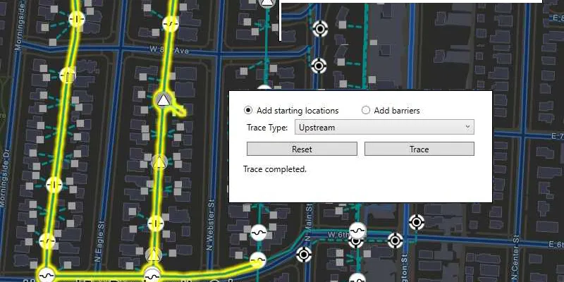
Upstream —In a source-based network (gas or electric), an upstream trace is against the flow and toward the source, such as a circuit breaker or generator ( subnetwork
A subnetwork is a subpart of a utility network tier, where all connected features are defined by the same subnetwork controller(s). controller). In a sink-based network (sewer or storm water), an upstream trace is against the flow and away from the sink, such as a sewage treatment (subnetwork controller). For more information, see ArcGIS Pro’s help topic upstream traces. -
Downstream —In a source-based network, a downstream trace is with the flow and away from the source, such as a circuit breaker or generator. In a sink-based network, a downstream trace is with the flow and toward the sink. For more information, see ArcGIS Pro’s help topic downstream traces.
-
Subnetwork —A trace that discovers all features
A feature is a single record, also known as a row, that represents a real-world entity. It typically contains a geometry (point, multipoint, polyline, or polygon) and attributes but it can also contain just attributes. participating in a subnetwork. This trace type is useful for validating whether subnetworksA subnetwork is a subpart of a utility network tier, where all connected features are defined by the same subnetwork controller(s). , such as circuits or zones, are defined or edited appropriately. The trace begins at one or more starting points and spans outward along connected features to find subnetwork controllersA subnetwork controller is a type of utility network feature from which a resource is delivered or collected, such as a circuit breaker (electric), town border stations (gas), or water towers (water). that are traversable. A subnetwork trace stops when it encounters a barrier, when it encounters a feature that is not traversable, or when there are no more connected features. For more information see ArcGIS Pro’s help topic subnetwork trace. -
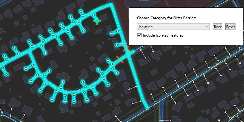
Isolation —A trace used to determine the minimum set of operable assets (point and line features) required to stop a network’s resource from traveling/flowing, effectively isolating an area of the network. For instance, when a leak occurs on a water network, particular valves must be closed to eliminate water flow at the leak location. This prevents damage and allows field crews to safely start the repair process. For more information, see ArcGIS Pro’s help topic locate isolating features.
-
Connected —A trace that begins at one or more starting points and spans outward radially along connected features. The trace stops when a barrier is encountered or there are no more connected features. A connected trace can be used to validate newly edited features to ensure that they are connected as expected. For more information, see ArcGIS Pro’s help topics connectivity and finding connected features.
-
Shortest path —A trace that finds the shortest path between two points in the network. The shortest path is calculated using a numeric network attribute such as shape length. Cost- or distance-based paths can be implemented using this type of trace. For more information, see Discover the shortest path tool in the ArcGIS Pro help.
-
Loops —Loops are areas of the network where flow direction is ambiguous. Within a loop, resources can flow in either direction. Loops are expected with mesh networks but usually indicate error conditions in radial networks. You can also discover loops using a shortest path trace. For more information, see Discover network loops in the ArcGIS Pro help.
Trace functionality
The following are the currently available functionalities (capabilities and types of traces and results) for a utility network from a feature serviceGeodatabaseSyncTask or OfflineMapSyncTask. Using the system tables only extract, the mobile geodatabase is editable but the utility network is not traceable; using a topology extract, the mobile geodatabase is read-only but the utility network is traceable.
| Editable Utility Network (system tables) | Traceable Utility Network (system and topology tables) | Stand-alone mobile geodatabase | Feature Service | |
|---|---|---|---|---|
| Query associations | | | | |
| Connected trace | | | | |
| Subnetwork trace | | | | |
| Upstream trace | | | | |
| Downstream trace | | | | |
| Isolation trace | | | | |
| Loops trace | | | | |
| Shortest path trace | | | | |
| Element trace result | | | | |
| Function trace result | | | | |
| Geometry trace result | | | | |
| Named trace configurations | | | | |